
Liquid crystal display device and electronic apparatus

a liquid crystal display and electronic equipment technology, applied in the field of liquid crystal display and electronic equipment, can solve the problems of difficult to obtain display with good coloring in transmisive mode, display is not readily visually recognized, and the display can suffer

Inactive Publication Date: 2002-10-24
BOE TECH GRP CO LTD
View PDF3 Cites 61 Cited by
  • Summary
  • Abstract
  • Description
  • Claims
  • Application Information

AI Technical Summary

Benefits of technology

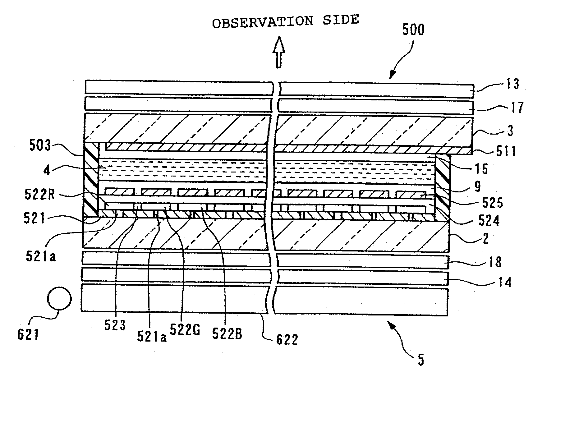
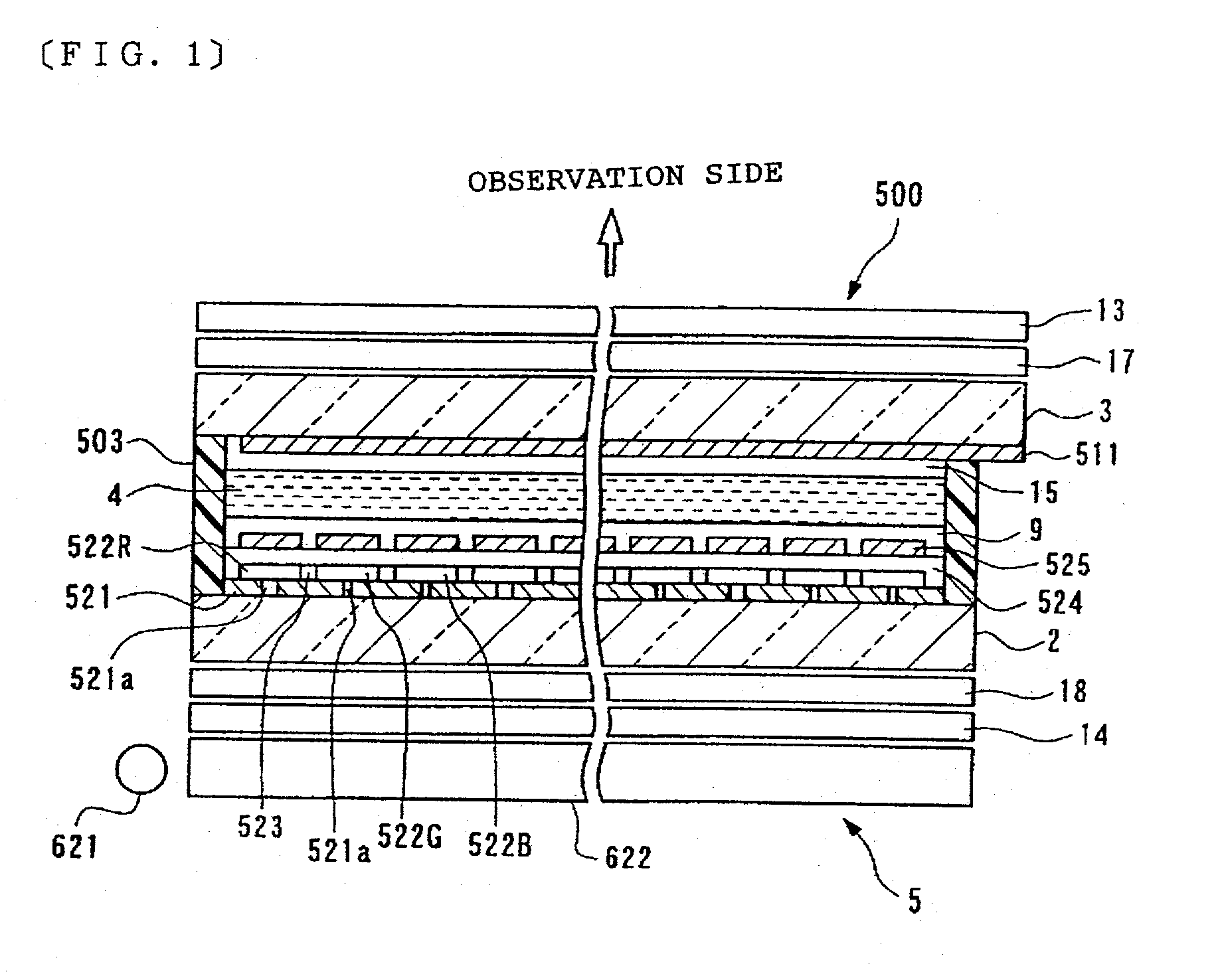
[0015] According to this liquid crystal display, the percentage of transmissive area of any one of the plurality of sub-pixels forming the pixels is made to differ from the percentage of transmissive area of other sub-pixels, thereby enabling the essential light transmittance of the sub-pixels as to the illumination light of the illumination device to be arbitrarily selected. Accordingly, even in the event that there are irregularities in the spectral properties of the illumination light (luminance and quantity of light of the illumination light at each wavelength, spectral energy, etc.), the irregularities of the spectral properties of the light emitted from the liquid crystal display panel towards the observation side can be reduced by compensating for the irregularities. Further, the percentage of the transmissive area of sub-pixels of one of the colors can be intentionally increased for a color of display by the liquid crystal display panel to be selected.
[0044] Also, in order to achieve the above objects, the electronic apparatus according to the present invention can include one of the above-described liquid crystal displays. For example, the liquid crystal display according to the present invention may be used as a display device in various types of electronic apparatuses, such as televisions or monitors, communication equipment such as cellular telephones or PDAs, information processing devices such as personal computers, and so forth. According to the electronic apparatus, even in the event that there are irregularities in spectral properties of the illumination light, this can be compensated to realize a display with high color reproduction, thereby yielding an electronic apparatus comprising a liquid crystal display with excellent visibility. Thus, this is suitable for an electronic apparatus requiring particularly high-quality display.

Problems solved by technology

Accordingly, reflective liquid crystal displays can suffer from the disadvantage that the display is not readily visually recognized in dark situations.
Accordingly, in the event that importance is given to display in the reflective mode where light passes through the color filter twice, for example, and accordingly a color filter with light colors is provided, display with good coloring cannot be readily obtained in the transmissive mode wherein the light passes through the color filter only once.
However, in the event that, in an attempt to solve this problem, importance is given to the transmissive mode where light passes through the color filter once, and accordingly a color filter with dark colors is provided, the display in the reflective mode where light passes through the color filter twice becomes dark, and consequently sufficient visibility cannot be obtained.
Thus, with conventional color transflective liquid crystal displays, it has been difficult to obtain a display with good coloring and high visibility both in the reflective mode and transmissive mode.
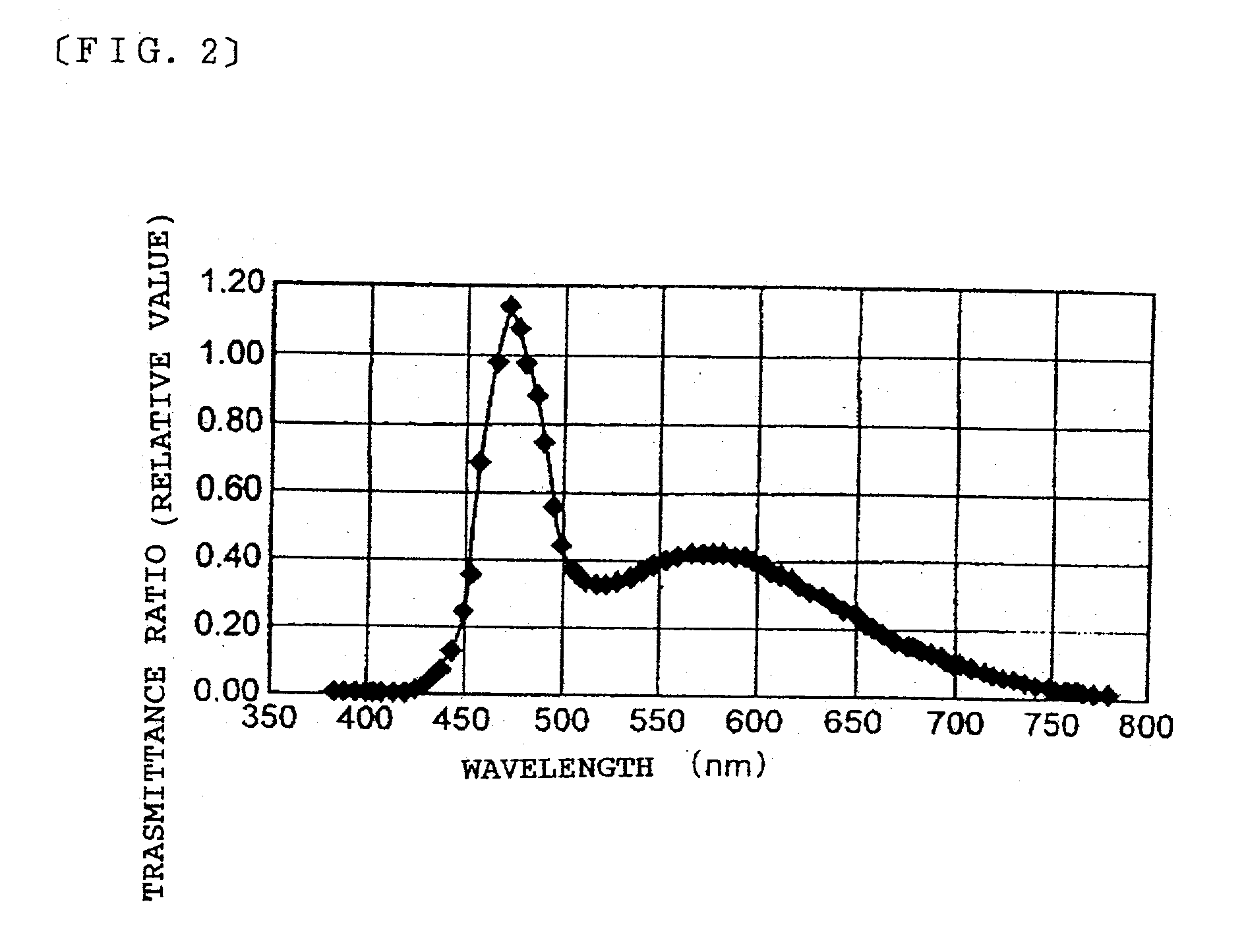
Also, illumination light emitted from illumination devices comprising LEDs (Light Emitting Diode) or cold cathode tubes or the like as a light source often do not have uniform luminance (intensity) throughout all wavelengths in the visible light range.
Using such light with non-uniform distribution in luminance to perform transmissive display can result also in nonuniformity of the spectral properties of light passing through the liquid crystal display panel and emitted towards the observation.
As a result, there has been the problem of deterioration in color reproduction that the display will be bluish in the case of using illumination light that has higher luminance in the wavelength corresponding to the blue color as compared to the luminance of other wavelengths, for example, to perform transmissive display.
Now, an arrangement wherein one opening portion is provided for each sub-pixel may be conceived, but in this case, opening portions will be concentrated on a part of the areas of the sub-pixels, which could lead to occurrence of graininess of the display.
With conventional transflective liquid crystal displays, increasing the transmittance by enlarging the transmissive area such that a bright display can be obtained in the transmissive mode, has the problem in that the reflectivity decreases and the display becomes dark in the reflective mode.
Thus, it has been difficult to realize a transflective liquid crystal display wherein a bright display can be obtained in both the reflective mode and transmissive mode.

Method used


Image

  • Liquid crystal display device and electronic apparatus
  • Liquid crystal display device and electronic apparatus
  • Liquid crystal display device and electronic apparatus

Examples


Embodiment Construction

26.3% 1.73 .times. 10.sup.-2 2.3% 1.50 .times. 10.sup.-2 Test Example 2 26.2% 1.55 .times. 10.sup.-2 2.3% 1.50 .times. 10.sup.-2 Test Example 3 34.1% 1.35 .times. 10.sup.-2 2.1% 0.50 .times. 10.sup.-2

[0276] Here, the term "color range dimension" means the dimension of a triangle formed by connecting the three points of the x, y coordinates of the red, green, and blue display colors on a CIE chromaticity diagram.

[0277] The liquid crystal display according to the test example 3 which is a comparative example has a narrow color range dimension for both the light obtained in the reflective mode and the light obtained in the transmissive mode, as can be seen from Table 1, FIG. 29, and FIG. 30.

[0278] Also, the liquid crystal display according to the test example 2 which is a comparative example, has a color range dimension wider in comparison with the liquid crystal display according to the test example 3 for both the light obtained in the reflective mode and the light obtained in the tra...


PUM

PropertyMeasurementUnit
wavelength rangeaaaaaaaaaa
colorsaaaaaaaaaa

Abstract

To provide a color transflective liquid crystal display that is capable of display with good coloring and high visibility in both a reflective mode and a transmissive mode while suppressing deterioration in color reproduction caused by unevenness of the spectral properties of the illumination light, if any. A liquid crystal display according to the present invention comprises a liquid crystal display panel including pixels 615 formed of a plurality of sub-pixels 551 each corresponding to different colors; and an illumination device, wherein the liquid crystal display panel comprises a transflective layer and a color filter 522 of color corresponding to each of the sub-pixels 511. The transflective layer comprises transmissive portions for transmitting illumination light, wherein the transmissive portion is formed such that the dimension of the transmissive area corresponding to the transmissive portion of at least one sub-pixel out of the plurality of sub-pixels 511 and the dimension of the transmissive area corresponding to the transmissive portion of another sub-pixel, differ.

Description

[0001] 1. Field of Invention[0002] The present invention relates to a liquid crystal display and to electronic apparatus, and particularly relates to a transflective liquid crystal display capable of display with good coloring and high visibility in both reflective mode and transmissive mode, and also relates to an electronic apparatus using the same.[0003] 2. Description of Related Art[0004] Currently, reflective liquid crystal displays are advantageous in that electric power consumption is low, since they do not have light sources such as back-lights, and have conventionally been widely used as accessory display units or the like for various types of mobile electronic apparatus and so forth. However, reflective liquid crystal displays use external light, such as natural light like sunlight, or illumination light, to perform display. Accordingly, reflective liquid crystal displays can suffer from the disadvantage that the display is not readily visually recognized in dark situation...

Claims


Application Information

Patent Timeline
Patent Type & Authority Applications(United States)
IPC IPC(8): G02B5/00G02B5/20G02F1/1335G02F1/13357G02F1/1362
CPCG02F1/133514G02F1/133555G02F1/1343G02F2201/52G02F2001/136222G02F2201/122G02F2001/133543G02F1/133543G02F1/136222G02F1/1335
Inventor IIJIMA, CHIYOAKI
Owner BOE TECH GRP CO LTD
Learn More