Optical pickup apparatus and optimal light spot focusing method

a pickup apparatus and optical technology, applied in the direction of optical beam sources, instruments, disposition/mounting of heads, etc., can solve the problem of changing the wavelength of light beams emitted from the light source,

Inactive Publication Date: 2002-10-31
TS OPTICS CORP
View PDF9 Cites 49 Cited by
  • Summary
  • Abstract
  • Description
  • Claims
  • Application Information

AI Technical Summary

Benefits of technology

0036] To achieve the above and other objects, there is provided a method of optimal focusing of a light spot by which seeking of an optimal focal point of a light spot is possible, the method according to another embodiment of the invention including detecting signals by dividing a light beam after being radiated from a light source onto a recording medium and reflected from the recording medium into first through fourth light regions in tangential and radial directions corresponding t

Problems solved by technology

Fourth, the wavelength of a light beam emitted from th

Method used


Image

  • Optical pickup apparatus and optimal light spot focusing method
  • Optical pickup apparatus and optimal light spot focusing method
  • Optical pickup apparatus and optimal light spot focusing method

Examples


Embodiment Construction

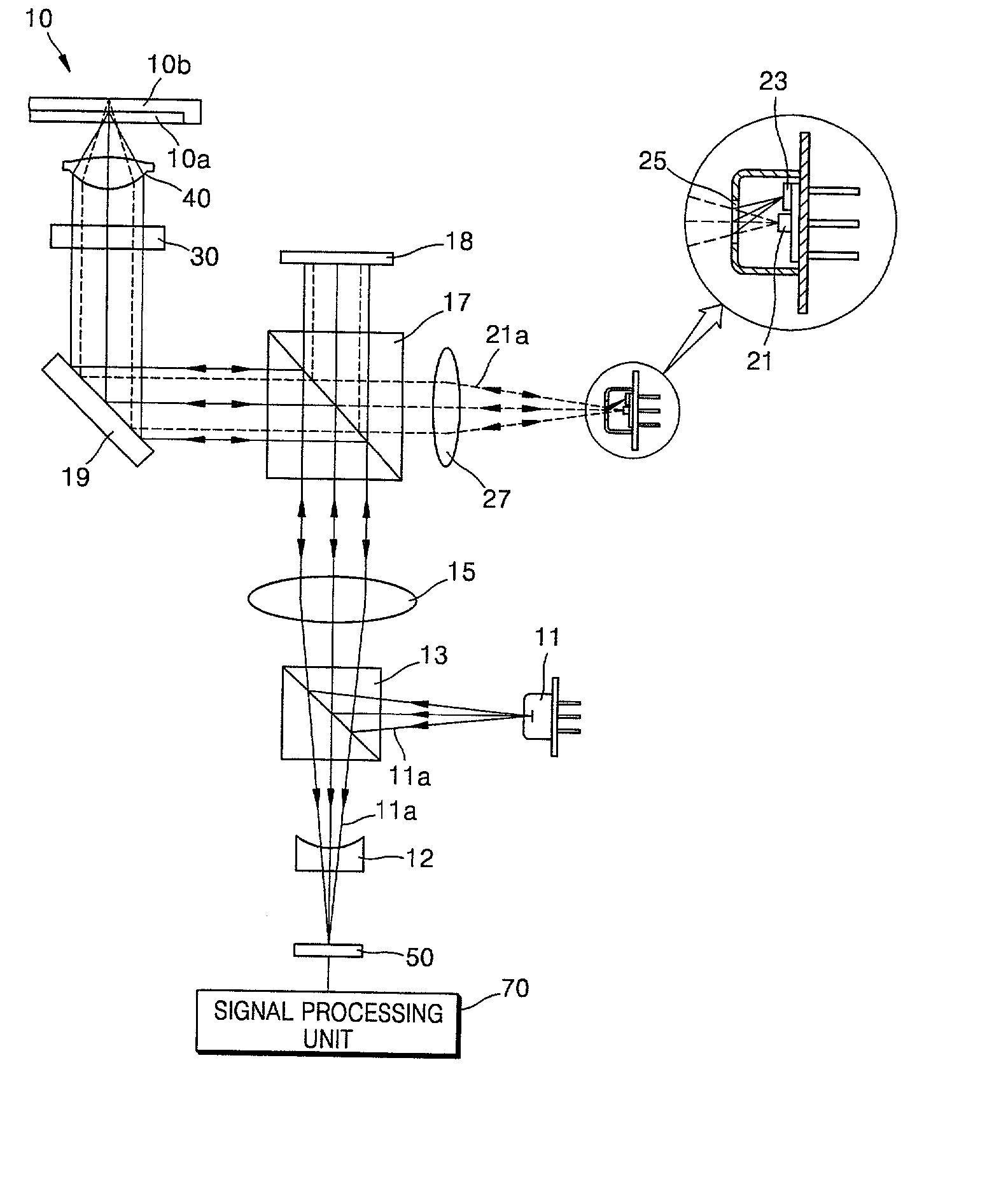
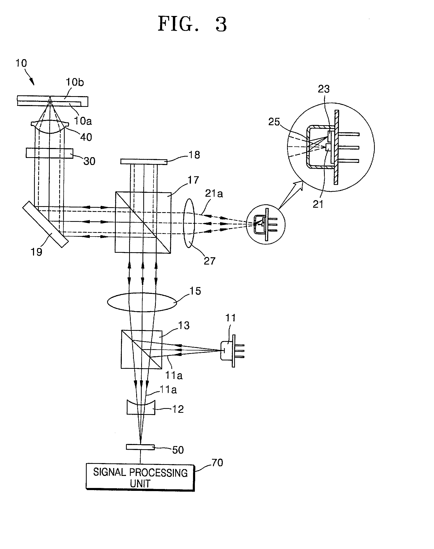
[0049] Reference will now be made in detail to the present preferred embodiments of the present invention, examples of which are illustrated in the accompanying drawings, wherein like reference numerals refer to the like elements throughout. The embodiments are described below in order to explain the present invention by referring to the figures.

[0050] In the embodiments described below, although an optical pickup apparatus according to an embodiment of the present invention is shown to be configured to compatibly use CD family optical discs and DVD family optical discs, the present invention is not limited thereto and is understood to be used with other optical recording media. For instance, the technology according to the present invention can be used in an optical pickup apparatus which can compatibly use the DVD family optical discs, next generation DVD family optical discs. Also, the present technology can be applied to an optical pickup apparatus for use optical discs of only ...


PUM


Abstract

An optical pickup apparatus includes a first light source to emit a first light beam having a predetermined wavelength, a first optical path changer to change a proceeding path of the first light beam, an objective lens to focus the first light beam on a recording medium, a diffraction member to divide the first light beam reflected by the recording medium into five light regions, the diffraction member having a first diffraction region having a wide width in a direction corresponding to a tangential direction of the recording medium and second through fifth diffraction regions sequentially arranged around the outside of the first diffraction region in a direction corresponding to a radial direction of the recording medium, and a first photodetector having first through fifth light receiving portions to receive the first light beam reflected by the recording medium.

Description

[0001] This application claims the benefit of Korean Application No. 2001-19647, filed Apr. 12, 2001, in the Korean Intellectual Property Office, the disclosure of which is incorporated herein by reference.[0002] 1. Field of the Invention[0003] The present invention relates to an optical pickup apparatus that detects a tracking error signal and is not sensitive to the occurrence of an offset due to a shaking of an objective lens and a focus error signal in which the occurrence of an offset due to a deviation of a photodetector from a design location, a change in temperature, and / or a change in the wavelength of a light beam is reduced, and to a method of optimally focusing a light spot.[0004] 2. Description of the Related Art[0005] Accurate detection of a focus and / or tracking error signal in recording and / or reproduction of a high capacity disc is necessary to perform a stable servo function. In general, an optical pickup apparatus includes a light source, an objective lens to focu...

Claims


Application Information

Patent Timeline
IPC IPC(8): G11B7/09G11B7/00G11B7/007G11B7/095G11B7/12G11B7/125G11B7/1275G11B7/13G11B7/131G11B7/135G11B7/1353G11B7/1367G11B7/139G11B7/1392
CPCG11B7/00718G11B7/094G11B7/0941G11B7/0943G11B7/0946G11B7/0956G11B2007/0006G11B7/131G11B7/1353G11B7/1367G11B7/139G11B7/13922G11B7/1275G11B7/09
Inventor LEE, YONG-JAEGO, SUNG -ROSEONG, PYONG-YONGYANG, CHANG-JINSONG, GI-BONGMA, BYUNG-INLEE, JONG-KOOG
Owner TS OPTICS CORP
Why Eureka
Try Eureka