Elastomer and steel cord composite and process for producing the same

a technology of elastomer and steel cord, which is applied in the direction of transportation and packaging, chemical instruments and processes, coatings, etc., can solve the problems of shortening the life of tires, reducing fatigue resistance, and large volume of space inside the cord, so as to reduce the time of tire component assembly or the like, energy saving, and low cost

Inactive Publication Date: 2002-10-31
YOKOHAMA RUBBER CO LTD +1
View PDF10 Cites 72 Cited by
  • Summary
  • Abstract
  • Description
  • Claims
  • Application Information

AI Technical Summary

Benefits of technology

0027] The invention is for solving these problems. Objects of the invention are that the life of a single layer or 2-layer steel cord itself which is used as a reinforcement by being embedded in a tire or the like is prolonged by satisfactorily exhibiting corrosion resistance and fatigue resistance, the life of a tire or the like using the same as a reinforcement is prolonged, and curing time in tire component assembling or the like is shortened to attain energy saving and allow production at low cost.

Problems solved by technology

As a result, corrosion proceeds from inside the cord, which might decrease fatigue resistance of the steel cord to shorten the life of the tire.
Nevertheless, the open-type steel cord has, in comparison with the close-type steel cord, a large volume of the space inside the cord, and an amount of air remaining within the cord is large.
Accordingly, an amount of air incorporated in a rubber at the time of tire component assembling is increased, and air pushed out from inside the cord in tire component assembling remains as voids (air trapping) in the tire rubber which results in damaging the strength of the tire body.
Therefore, for diffusing such air and eliminating voids, it is required to prolong curing time in tire component assembling, which decreases productivity and increases consumption energy.
However, with respect to the use of the core material such as the organic material or the like, both adhesion with rubber of a tire body and adhesion with steel filaments have to be taken into account, and designing is much restricted.
Thus, it is indeed disadvantageous in view of the technique and the cost.
As a result, a fretting abrasion occurs within the steel cord during use of the tire.
Further, moisture or the like incorporated into the tire owing to external damage or crack of the tire sometimes reaches the space in the central portion of the strand.
The moisture is permeated in a longitudinal direction of the cord by capillarity, and corrosion proceeds within the cord.
Consequently, properties (strength and fatigue resistance) of the steel cord in the tire are notably decreased to shorten the product life of the tire.
Moreover, the influence of the space remaining within the steel cord is not only that, but air remaining in the space is exhausted in tire component assembling to cause air trapping, and this air remains in the rubber to impair the strength of the tire body too.
Accordingly, for diffusing such air and eliminating air trapping, a curing time has to be prolonged in tire component assembling, which decreases productivity and increases consumption energy.
In such a structure, however, it is also difficult to completely fill the spaces within the steel cord with the rubber.
In comparison with tight stranding, a life of a tire can slightly be prolonged, however not satisfactory.
Further, in the 2-layer steel cord obtained by stranding the outer layer filaments around the core strand, stranding is conducted in 2 steps, which involves high production cost.
However, the rubber hardly permeates the inside of the cord in tire component assembling.
As a result, a fretting abrasion also occurs within the steel cord during use of the tire, and moisture or the like enters the inside of the steel cord owing to external damage in the tire surface, which might decrease fatigue resistance of the tire cord to shorten the life of the tire.
Air remaining in the spaces in the central portion is exhausted in tire component assembling to cause air trapping, and this air remains in the rubber to impair the strength of the tire body.
For diffusing such an air and eliminating air trapping, a curing time has to be prolonged in tire component assembling, which decreases a productivity and increases a consumption energy.
However, in this structure, it is also hard to completely fill the spaces inside the cord with the rubber.
The life of the tire can slightly be prolonged, however not satisfactory.
Thus, designing is much restricted.
It is indeed disadvantageous in view of the technique and the cost.
In the ordinary single layer steel cord obtained by stranding 3 to 6 steel filaments, especially in case of the close type, there is a problem that the space in the central portion of the cord remains as a hollow portion in tire component assembling or the like and moisture or the like enters the hollow portion to cause corrosion from inside the cord.
For diffusing this air and eliminating voids, the curing time has to be prolonged, posing a problem of consuming huge energy.
Moreover, when the space in the central portion of the close-type cord is filled with a nonmetallic core material, adhesion between the core material and the rubber of the tire body and adhesion with steel filaments have to be taken into account, which is disadvantageous in view of the technique and the cost.
In addition, in the ordinary 2-layer steel cord, the spaces are formed in the central portion of the core strand and inside the outer layer filaments (between the outer layer filaments and the core strand), and a sufficient amount of rubber does not permeate the inside of the cord in tire component assembling.
Consequently, a fretting abrasion occurs inside the steel cord during use of the tire.
Accordingly, corrosion proceeds from inside, which might notably decrease strength or fatigue resistance of the steel cord in the tire to shorten the life of the tire.
Further, when air in the spaces inside the steel cord remains in the rubber owing to air trapping, the strength of the tire body is impaired.
For eliminating the air trapping, curing time has to be prolonged in tire component assembling, which poses problems of decreasing productivity and increasing consumption energy.
Even when the number of outer layer filaments is decreased, for solving these problems, to provide spaces between filaments for facilitating permeation of the rubber, it is difficult to completely fill the space in the central portion of the core strand with the rubber.
Further, in the 2-layer steel cord of 1 stranding process for decreasing the production cost, drop occurs in the outer layer filaments, and the spaces between the filaments are in a close state, which causes fretting abrasion and decreases fatigue resistance by incorporation of moisture or the like.
For eliminating air trapping, curing time has to be prolonged, which poses problems of decreasing productivity and increasing consumption energy.
Still further, in the use of the water-absorbent polymer, the organic material and the like, both the adhesion with the rubber of the tire body and the adhesion with the steel filaments have to be taken into account, which is disadvantageous in view of the technique and the cost.

Method used


Image

  • Elastomer and steel cord composite and process for producing the same
  • Elastomer and steel cord composite and process for producing the same
  • Elastomer and steel cord composite and process for producing the same

Examples


2nd example

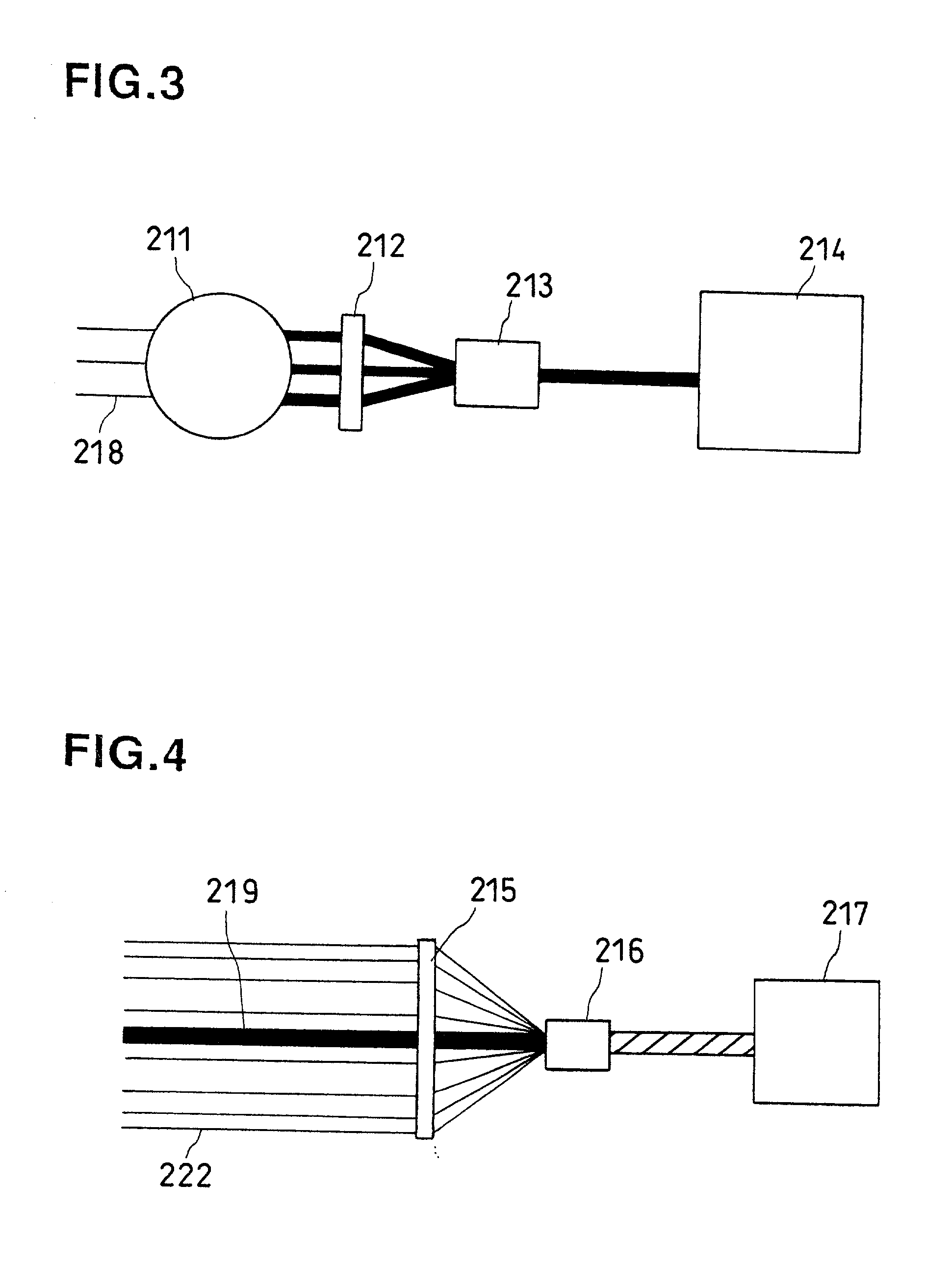
[0080] FIG. 3 and FIG. 4 show a process for producing an elastomer and steel cord composite in 2nd Example of the invention. This example is a case of producing a 3 +9 structure of elastomer and steel cord composite. The process comprises a step of forming a core strand (shown in FIG. 3) and a step of stranding outer layer filaments around the core strand (shown in FIG. 4). In FIG. 3, 211 is an uncured rubber coating unit, 212 a wire separator, 213 an inlet die and 214 a buncher (double twist stranding machine). In FIG. 4, 215 is a wire separator, 216 an inlet die and 217 a buncher (double twist stranding machine). All the units are those known per se.

[0081] In the step of forming the core strand as shown in FIG. 3, 3 steel filaments 218 as core filaments are fed in parallel, and supplied toward an inlet of the buncher (double twist stranding machine) 214. During the supply, each of the 3 steel filaments 218 is coated with an uncured rubber through the uncured rubber coating unit 21...

3rd example

[0087] FIG. 7 shows a step of producing an elastomer and steel cord composite in 3rd Example of the invention. This 3rd example is a case of producing a 3 / 9 structure of elastomer and steel cord composite. In FIG. 7, 324 is an uncured rubber coating unit, 325 and 326 wire separators, 327 an inlet die and 328 a buncher (double twist stranding machine). All the units are those known per se.

[0088] In this 3rd Example, 3 steel filaments 329 as core filaments and 9 steel filaments 330 as outer layer filaments are simultaneously fed in parallel such that the 3 steel filaments 329 as core filaments are arranged inside and the 9 outer steel filaments 330 as outer layer filaments are arranged therearound, and supplied toward an inlet of the buncher (double twist stranding machine) 328. During the supply, the uncured rubber is coated on the 3 steel filaments 329 as core filaments with the uncured rubber coating unit 324, passed through the former separator 325, and gathered in the latter wire...

4th example

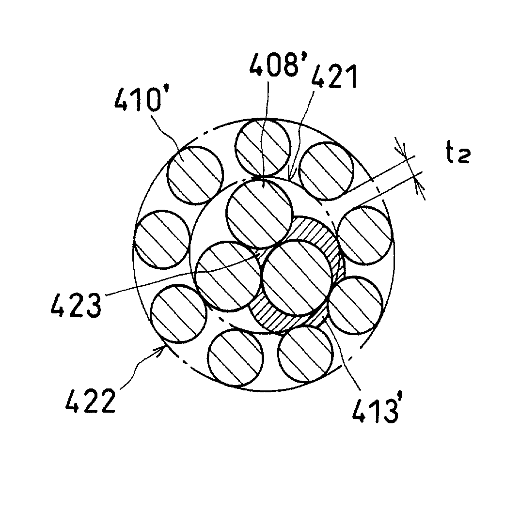
[0092] FIG. 9 and FIG. 10 show a process for producing an elastomer and steel cord composite in 4th Example of the invention. This example is a case of producing a (3+8) structure of elastomer and steel cord composite. The process comprises a step of forming a core strand (shown in FIG. 9) and a step of stranding outer layer filaments around the core strand (shown in FIG. 10). In FIG. 9, 401 is an uncured rubber coating unit, 402 a wire separator, 403 an inlet die and 404 a buncher (double twist stranding machine). In FIG. 10, 405 is a wire separator, 406 an inlet die and 407 a buncher (double twist stranding machine). All the units are those known per se.

[0093] In the step of forming the core strand as shown in FIG. 9, 3 steel filaments 408 as core filaments are fed in parallel, and supplied toward an inlet of the buncher (double twist stranding machine) 404. During the supply, at least one of the 3 steel filaments 408 is coated with an uncured rubber through the uncured rubber coa...


PUM

PropertyMeasurementUnit
diameteraaaaaaaaaa
corrosion resistanceaaaaaaaaaa
fatigue resistanceaaaaaaaaaa

Abstract

In order that spaces, including a space in the central portion, inside a steel cord used as a reinforcement by being embedded in a tire or the like are filled with an uncured rubber, the uncured rubber is coated on plural steel filaments 115 which are then stranded in case of a single layer steel cord, the uncured rubber is coated on all of plural core filaments 329 which are then stranded along with outer layer filaments 330 in the same direction at the same pitch in case of a 2-layer steel cord of 1 stranding process, and the uncured rubber is coated on all or 2 to 4 core filaments 218 or on at least one of 3 or 4 steel filaments 408, 408' to form a core strand and outer layer filaments 410, 410' are stranded therearound in case of 2-layer steel cord of 2 stranding process. Consequently, it is possible to exhibit satisfactory corrosion resistance and satisfactory fatigue resistance as a steel cord, shorten a curing time in tire component assembling or the like to attain energy saving and prolong the life of a steel cord itself and the life of a tire or the like using the same as a reinforcement. Further, production can be performed at low cost.

Description

[0001] 1. Field of Invention[0002] The present invention relates to a steel cord which is used as a reinforcement by being embedded in a tire or the like, and a process for producing the same. More specifically, it relates to an elastomer and steel cord composite which, when used as, for example, a tire reinforcement, can exhibit a satisfactory corrosion resistance and a satisfactory fatigue resistance and which can shorten a curing time in tire component assembling and attain energy saving, and a process for producing the same.[0003] 2. Description of the Prior Art[0004] A single layer close-type steel cord obtained by stranding, for example, 3 to 6 filaments (steel filaments) has been so far used as a steel cord for tire reinforcement. FIG. 13 shows a sectional view of a so-called 1.times.3 steel cord 12 obtained by tightly stranding 3 steel filaments 11 as an example of such close-type steel cord.[0005] In the single layer steel cord obtained by stranding 3 to 6 steel filaments, ...

Claims


Application Information

Patent Timeline
Patent Type & Authority Applications(United States)
IPC IPC(8): D07B1/16B32B5/08B32B5/26
CPCB32B5/08B60C2009/0021D07B1/062D07B1/0626D07B7/145D07B2201/2012D07B2201/2022D07B2201/2023D07B2201/2024D07B2201/2028D07B2201/2032D07B2201/2039D07B2201/2046D07B2201/2061D07B2201/2062D07B2201/2081D07B2205/2075D07B2207/204D07B2501/2046B32B5/26B60C9/0007B29K2305/12B29K2105/246B29K2021/00B29B15/14D07B2801/12D07B2801/18Y10T428/31707D07B1/16
Inventor IMAMIYA, SUSUMUYOSHIDA, SATOSHI
Owner YOKOHAMA RUBBER CO LTD
Why Eureka
Try Eureka