Selective cutting one shot

Inactive Publication Date: 2002-11-07
VISTEON GLOBAL TECH INC
View PDF11 Cites 12 Cited by
  • Summary
  • Abstract
  • Description
  • Claims
  • Application Information

AI Technical Summary

Benefits of technology

0007] The aim of the present invention is to provided a process and a device for forming a planiform piece, intended, in particular,

Problems solved by technology

It will be noted that such a process necessitates two manufacturing stages, one to produce t

Method used


Image

  • Selective cutting one shot
  • Selective cutting one shot
  • Selective cutting one shot

Examples


Embodiment Construction

[0021] The invention relates firstly to a process for forming a planiform piece.

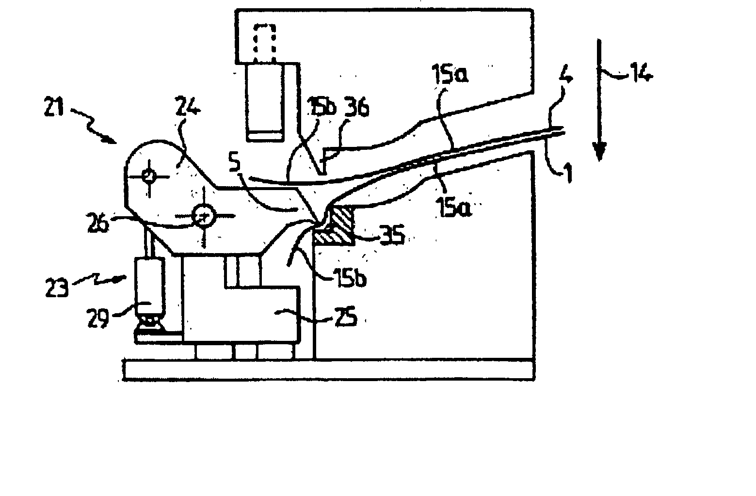
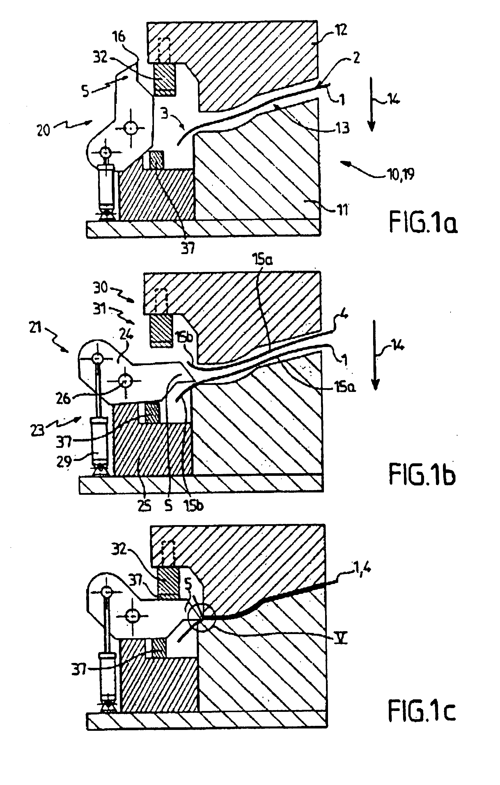
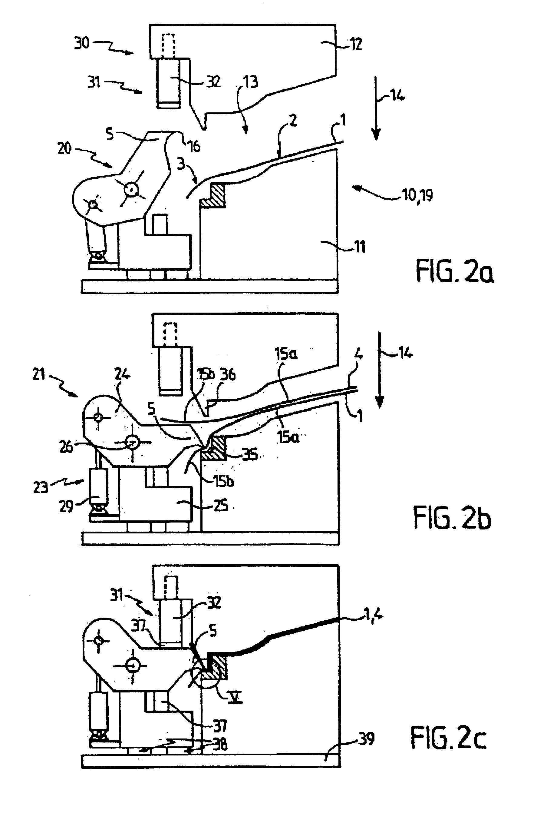
[0022] As illustrated in FIGS. 1 to 4, according to the process of the invention, a layer of material, in particular fibrous material, defining a support 1 is covered by a cladding sheet 4 on at least one of its faces 2 and in the area of a portion 3, at least, of its contour, or so-called `portion to be bordered`.

[0023] Said support is intended, for example, to impart its form to the piece thus obtained, while cladding 4 serves, in particular, to enhance its appearance. The latter is constituted, for example, by a multi-layer material including, in particular, a thickness of non-woven fabric, a thickness of foam and a thickness of textile. Said cladding 4 is provided, for example, over the entire surface of said face 2 and / or over all of its contour.

[0024] Said support 1 is cut along said portion to be bordered 3 in such a way that said cladding 4 projects beyond said support 1 in the area of said porti...


PUM

PropertyMeasurementUnit
Areaaaaaaaaaaa

Abstract

The invention relates to a process and a device for forming a planiform piece intended, in particular, for the interior fittings of motor vehicles, in which a layer of support material (1) is covered, at least on one of its faces (2) and in the area of a portion (3), at least, of its contour, or so-called portion to be bordered, with a cladding sheet (4) and said support (1) is cut along said portion to be bordered (3) in such a way that said cladding (4) projects from said support (1) in the area of said portion. According to the invention, a cutting tool (5) is pre-positioned between said cladding (4) and said support (1) along said portion to bordered (3) said cutting is effected with said cutting tool (5), when the support (1) is covered by the cladding (4).

Description

[0001] The invention relates to a process and a device for forming a planiform piece intended, in particular, for the interior fittings of motor vehicles.[0002] The expression "planiform piece" is to be taken as meaning a piece the thickness of which is very considerably smaller than the other dimensions, said piece not necessarily being flat, but possibly having inwardly and / or outwardly facing deformations.[0003] Although more especially intended for forming pieces designed for the interior trim of the bodywork of motor vehicle passenger compartments such as, for example, door panels, cabinet-work or dashboards, the invention can also be used to form pieces intended for any other field.[0004] There are presently known pieces constituted by a support layer of fibrous material lined, on one of their faces, with a cladding sheet which borders the support along its contour.[0005] To obtain such pieces, the support of the cladding sheet is formed, and then the support is cut out along ...

Claims


Application Information

Patent Timeline
IPC IPC(8): B29C43/40B29C51/08B29C51/14B29C51/32B32B38/10
CPCB29C43/40Y10T29/5102B29C51/14B29C51/32B29C2793/009B29L2009/00B29L2009/001B29L2031/3014B32B38/10Y10T29/49867Y10T29/53787Y10T29/49869Y10T156/1052Y10T29/5103Y10T29/5148B29C51/082Y10T83/8798
Inventor SAELEN, MARCDELATTRE, JEAN-YVESFREYCON, BERNARD
Owner VISTEON GLOBAL TECH INC
Why Eureka
Try Eureka