
Fuel-injection system for internal combustion engines

a technology for internal combustion engines and injection systems, which is applied in the direction of fuel injection pumps, liquid fuel feeders, machines/engines, etc., can solve the problems of difficult assembly of force-compensated valves with multi-part valve bodies, use of slide valves,

Inactive Publication Date: 2002-11-07
ROBERT BOSCH GMBH
View PDF0 Cites 0 Cited by
  • Summary
  • Abstract
  • Description
  • Claims
  • Application Information

AI Technical Summary

Benefits of technology

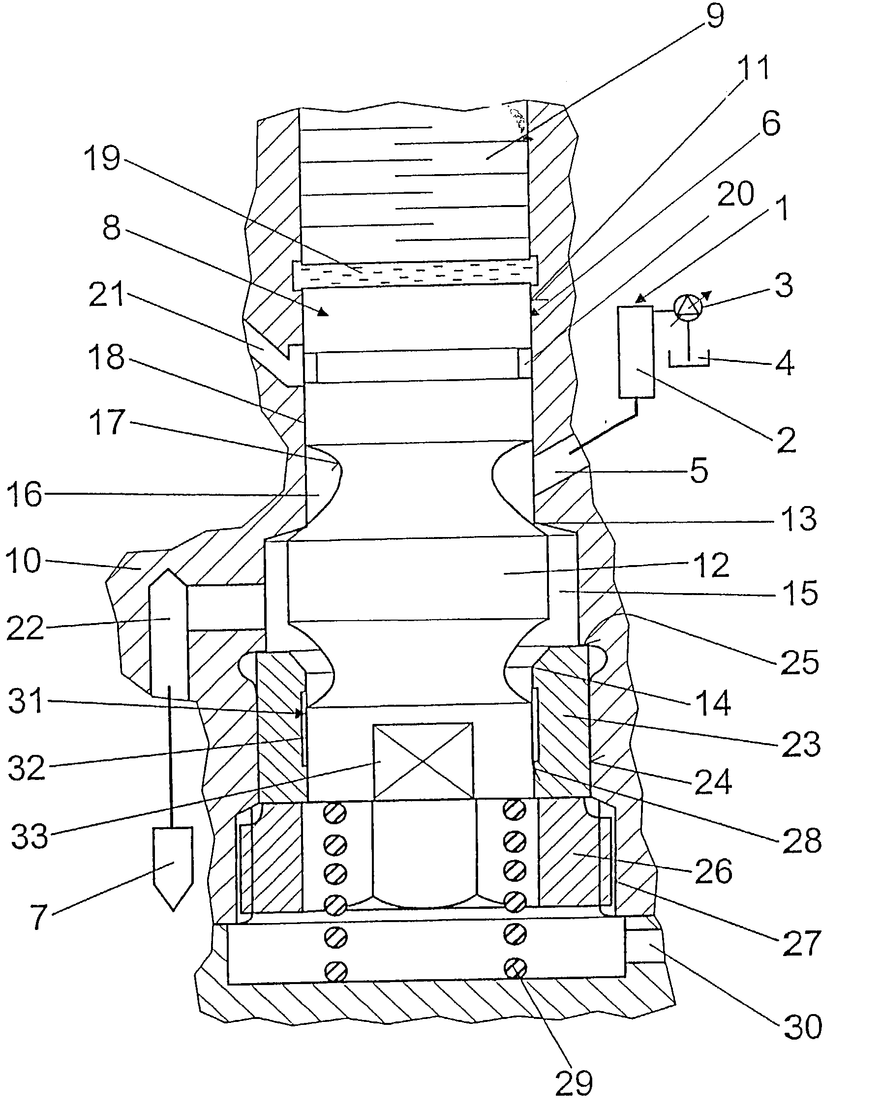
[0005] The fuel injection apparatus according to the invention, with the features of claim 1, has the advantage that the control valve is provided as a precisely functioning 3 / 2-way valve in a pressure-controlled system, which valve can be directly actuated by a piezoelectric unit by means of a mechanical transmission and in a particularly advantageous manner, by means of a hydraulic transmission. The integration of the control valve into the inlet of fuel into the injection opening of the fuel injection apparatus permits short injections that can be precisely metered.[0006] A significant advantage of the fuel injection apparatus according to the invention lies in the design of the control valve, which permits the realization of the valve with essentially one valve body into which a component that is suitable for embodying the second valve seat and the second guide can be inserted, preferably a sleeve according to claim 3.[0007] Embodied in a correspondingly simple manner, the assembly of the control valve, particularly the valve body and the opposing piece that constitutes the second valve seat, e.g. the sleeve according to claim 3, can be advantageously produced in one chucking operation. This achieves a high degree of precision fit of the components with one another.[0008] Other advantages and advantageous embodiments of the invention ensue from the claims and the exemplary embodiment that is described in principle below in conjunction with the drawing.

Problems solved by technology

The use of slide valves, which have control edges for covering and uncovering inlets and outlets, however, is disadvantageous due to the large leakages, which result from the usually small overlap.
However, the complex embodiment of the valve housing with a number of mold joints has proven to be problematic, where it turns out to be particularly difficult to assemble a force-compensated valve with a multi-part valve body.

Method used


Image

  • Fuel-injection system for internal combustion engines
  • Fuel-injection system for internal combustion engines

Examples


Embodiment Construction

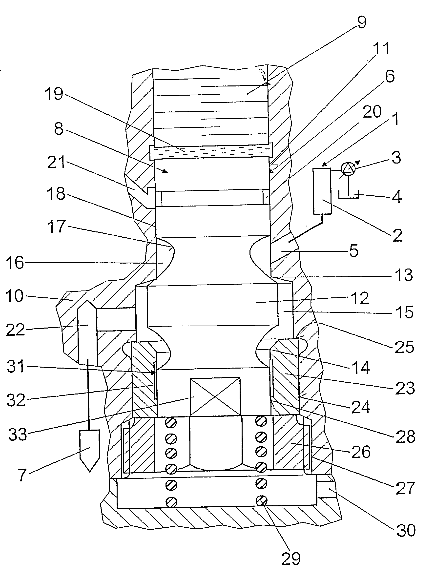
[0010] The exemplary embodiment shown in the FIGURE is a fuel injection apparatus for internal combustion engines of motor vehicles, which is embodied as a common rail injector for injecting diesel fuel. The common rail system represents a high-pressure fuel source 1, which is embodied with a high-pressure fuel reservoir 2, which a high-pressure fuel-supply pump 3 supplies with fuel from a fuel tank 4, which has been compressed to an injection pressure.

[0011] A line 5 leads from the high-pressure fuel reservoir 2 to a control valve 6, which in turn conveys the fuel to an injection opening 7 for injection; this injection opening is only symbolically indicated in the FIGURE and can be conventionally embodied as a nozzle holder device.

[0012] In order to adjust an injection onset, an injection duration, and a fuel injection quantity by means of the fuel supply, the control valve 6 is embodied with a valve member 8, which is controlled by means of a piezoelectric unit embodied as a piezo...


PUM


Abstract

A fuel injection apparatus for internal combustion engines conveys fuel from a high-pressure fuel reservoir (1) to an injection opening (7) by means of a control valve (6), which can be actuated by a piezoelectric unit (9). The control valve (6) has a valve member (8), which can be moved axially between a first valve seat (13) and a second valve seat (14), which define a first valve chamber (15). A line (5) leading from the high-pressure fuel source (1) feeds into a second valve chamber (16), which is defined by the first valve seat (13) and a first guide (18) of the valve member (8) in the valve body (10). A line (2), which leads to the injection opening (7), branches from the first valve chamber (15). A second guide (28) of the valve member (8) is provided in a region of the valve member (8) adjacent to the second valve seat (14). On the respective side of each guide (18, 28), a respective leakage line (21, 30) is provided. The diameters of the valve seats (13, 14) and the guides (18, 28) are respectively selected to be the same so that a force compensation is achieved in the control valve (6) (FIGURE).

Description

PRIOR ART[0001] The invention relates to a fuel injection apparatus for internal combustion engines in which fuel is conveyed from a high-pressure fuel source to an injection opening via a control valve. In fuel injection apparatuses of this kind, which are extensively known from the prior art and are particularly used in common rail systems, the supply of fuel to the injection opening, which is usually embodied as a nozzle holder device, is frequently controlled by means of a slide valve or seat / slide valve, which can be embodied as force-compensated or partially force-compensated. The use of slide valves, which have control edges for covering and uncovering inlets and outlets, however, is disadvantageous due to the large leakages, which result from the usually small overlap.[0002] One way to avoid these disadvantages is to use a double seat valve, which has the advantage over slide valves that the stroke length is considerably increased and in which a high degree of sealing action...

Claims


Application Information

Patent Timeline
IPC IPC(8): F02M51/06F02M47/00F02M59/46F02M61/16F02M63/00
CPCF02M63/0026F02M63/0007
Inventor BOECKING, FRIEDRICH
Owner ROBERT BOSCH GMBH
Learn More