
Battery capacity calibration

a rechargeable battery and capacity technology, applied in secondary cell servicing/maintenance, instruments, transportation and packaging, etc., can solve the problems of inability to accurately estimate, difficult to accurately measure, and inability to accurately measure the accuracy of fuel gauges

Inactive Publication Date: 2002-11-14
HIGHBRIDGE PRINCIPAL STRATEGIES LLC AS COLLATERAL AGENT
View PDF0 Cites 32 Cited by
  • Summary
  • Abstract
  • Description
  • Claims
  • Application Information

AI Technical Summary

Benefits of technology

[0018] With the present invention, an accurate calibration of the battery can be carried out in a relatively short period of time during charging of the battery. For example, mobile telephones manufactured by the assignee of the present invention charge batteries using a fast charging algorithm, such that a complete charging cycle typically lasts no more than 1-2 hours. With the present invention, therefore, the battery can also be accurately calibrated in this period of time. In general, it is contemplated that a calibration according to the present invention will be carried out automatically during a typical overnight charging cycle so as to minimize possible inconvenience to the user.
[0022] According to a further embodiment of the invention, it is not necessary to completely discharge the battery before the charging process is begun. Instead, a value representing the remaining capacity of the battery before it is charged is provided, and this value is added to the total amount of charge accepted by the battery during the charging process to provide the total battery capacity value.
[0024] In general, by providing a reliable value for the remaining capacity of the battery, complete discharge of the battery before charging is unnecessary. This can both simplify and speed up the overall calibration procedure somewhat.
[0027] When a calibration procedure according to the present invention indicates that the total capacity value of the battery should be adjusted, it is preferred that the adjustment, whether it be an increase or a decrease in the value, be by no more than some maximum amount pursuant to any one calibration even if the results of the calibration indicate that a greater adjustment is needed. Such maximum amount can, for example, be a percentage of the previously stored total battery capacity value (e.g., 10%), a percentage of the amount of the adjustment indicated as being needed (e.g., 25-50%), or some other selected amount. By limiting the amount of the adjustment as a result of any one calibration, if an erroneous calibration does occur, it will have only a limited impact on the performance of the fuel gauging algorithm used by the device; and, in addition, it will prevent extreme adjustments to the total battery capacity value that might be noticeable to the user.
[0028] The present invention generally provides a calibration method and apparatus that can make fuel gauging more accurate than in many prior techniques, and that can more reliably provide the user of an electronic device with better information regarding the remaining operational time of the device. One reason for the increased accuracy is that errors that do occur during a calibration procedure tend to be cumulative in nature. Because, in the present invention, calibration can usually be done in less time than by prior methods, fewer errors are likely to occur such that the accumulated errors are also likely to be less.
[0029] In general, the present invention also provides a calibration procedure that is fully automatic and does not require any interaction from the user, other than the user initiating the normal process for charging the battery. The procedure is also fully adaptive inasmuch as a calibration will be performed at all available opportunities while, at the same time, a calibration will generally not be performed when there is a substantial risk of incorrect measurements. An important feature of the present invention is that it recognizes that different users of electronic devices have differing habits with respect to their use and handling of their devices; and endeavors to ensure that some type of calibration is periodically carried out irrespective of the user's habits. The procedure of the invention also provides a convenient means to monitor the degradation of the battery due to ageing and / or other factors.

Problems solved by technology

This difference can have a very significant negative impact on the accuracy of the fuel gauging.
Such an estimate, however, is only a rough estimate (a straight line estimate) and is not very accurate.
In general, battery ageing is a very unpredictable process and current battery ageing estimations are not sufficient to provide an accurate measure of remaining battery capacity; and, hence, prevent an accurate estimation of remaining operational time of a device using the battery.
In addition, if no dedicated hardware is added to the phone, the calibration procedure can take a very long time; and, since the phone normally cannot be used during the procedure, this can be a great inconvenience to the user.
Inasmuch, however, as mobile telephones may have a standby time of hundreds of hours, such a calibration procedure may require as much as several days.
Also, high or low battery temperatures or other factors can also interfere with the charging process so as to prevent the battery from being fully charged.
By limiting the amount of the adjustment as a result of any one calibration, if an erroneous calibration does occur, it will have only a limited impact on the performance of the fuel gauging algorithm used by the device; and, in addition, it will prevent extreme adjustments to the total battery capacity value that might be noticeable to the user.
One reason for the increased accuracy is that errors that do occur during a calibration procedure tend to be cumulative in nature.

Method used


Image

  • Battery capacity calibration
  • Battery capacity calibration
  • Battery capacity calibration

Examples


Embodiment Construction

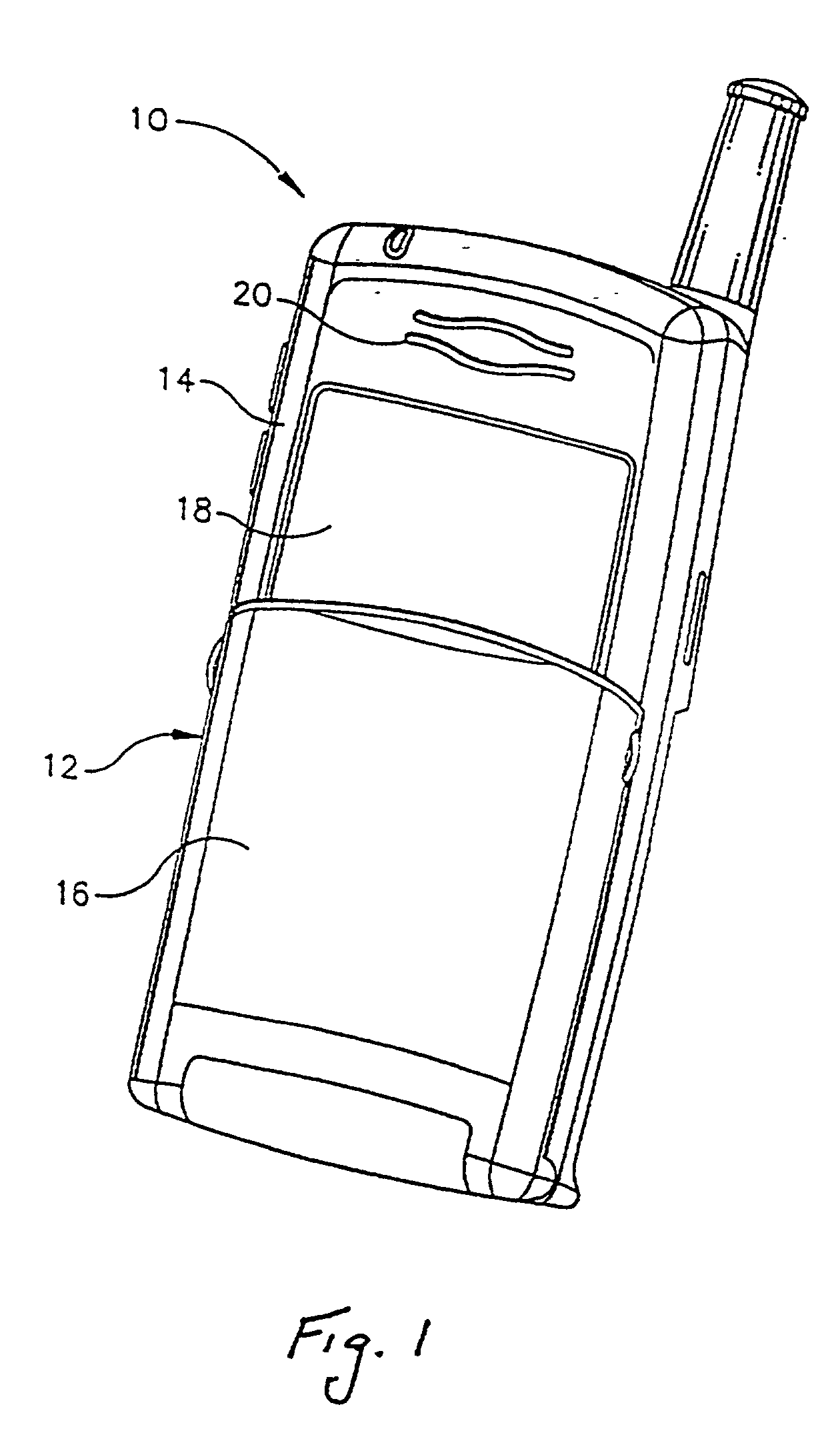
[0041] FIGS. 1 and 2 are front and rear perspective views, respectively, illustrating a mobile terminal in the form of a handheld mobile telephone used in a cellular telecommunications system. The telephone is generally designated by reference number 10; and includes a main housing 12 having a front surface 14 which provides access to a keypad (behind a cover 16 and, therefore, not shown), a display 18 and a speaker 20.

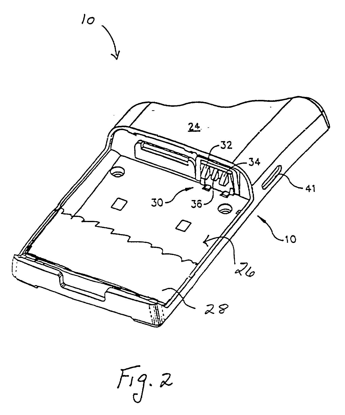
[0042] As best shown in FIG. 2, a rear surface 24 of housing 12 has a cavity 26 in which a battery 28 (only a portion of which is illustrated in FIG. 2) is adapted to be positioned. An interface 30 in the cavity, which includes three terminals 32, 34, and 36 in the illustrated telephone to permit the phone to be used with and to identify different types of batteries, is provided to electrically couple the battery and the telephone as is known to those skilled in the art.

[0043] The battery 28 can be of various types and constructions as is also known to those skilled i...


PUM

PropertyMeasurementUnit
battery currentaaaaaaaaaa
timeaaaaaaaaaa
currentaaaaaaaaaa

Abstract

Method and apparatus for calibrating a rechargeable battery for mobile telephones and other electronic devices. Calibration is accomplished during a process of completely charging the battery by determining the total amount of charge accepted by the battery during the charging process, and providing a value of total charge capacity of the battery based, at least in part, on the total amount of charge accepted by the battery. The total charge capacity of the battery is used to calculate remaining battery capacity and to predict the remaining operational time of the device. Alternative calibration procedures are provided if the battery is not completely discharged before charging or if the battery is not fully charged by the charging process. The calibration procedures of the invention require no interaction from a user (other than his initiating the normal charging process), and typically permits a calibration to be carried out notwithstanding varying usage habits of different users.

Description

[0001] This application claims the benefit of U.S. Provisional Application Serial No. 60 / 256,734 filed on Dec. 19, 2000.[0002] 1. Field of the Invention[0003] The present invention relates generally to the field of battery powered electronic devices; and, more particularly, to a method and apparatus for calibrating a rechargeable battery for mobile telephones and other portable electronic devices.[0004] 2. Description of the Prior Art[0005] Many types of electronic devices utilize battery power instead of or in addition to A / C power from an outlet. For example, mobile telephones and other mobile terminals, laptop computers, camcorders, etc., usually utilize rechargeable batteries; and a variety of types of rechargeable batteries have been developed for use in such applications including nickel-cadmium batteries, nickel metal hydride batteries and lithium ion batteries.[0006] A user of a portable electronic device often wishes to know the operational time remaining with an installed ...

Claims


Application Information

Patent Timeline
Patent Type & Authority Applications(United States)
IPC IPC(8): G01R31/36H01M10/44
CPCG01R31/3624H01M10/44G01R31/3648G01R31/3842Y02E60/10
Inventor PTASINSKI, KRISTOFFERFORSBERG, CHARLESKALOGEROPOULOS, SARANDISANDERSSON, RICKARDEVERS, PETRUSLANGBERG, ANDERSDEMERS, DAVIDCARLSON, JEREMYLIDDLE, DEREK
Owner HIGHBRIDGE PRINCIPAL STRATEGIES LLC AS COLLATERAL AGENT
Learn More