Piezoactuator and drive circuit therefor

a technology of actuator and drive circuit, which is applied in the direction of piezoelectric/electrostrictive device details, instruments, device details, etc., can solve the problems of limiting the thickness of wristwatches, and the conventional calendar display mechanism using a stepping motor is therefore not suited to wristwatches that must be made thin, and is particularly difficult to achiev

Inactive Publication Date: 2002-11-21
SEIKO EPSON CORP
View PDF6 Cites 19 Cited by
  • Summary
  • Abstract
  • Description
  • Claims
  • Application Information

AI Technical Summary

Problems solved by technology

First, there are watches with a calendar display mechanism provided in the watch, and there are watches that are not equipped with a calendar display mechanism.
While there has thus been a strong desire for thinning the calendar display mechanism, the stepping motors used in the calendar display mechanism are configured such that the coil and rotor and such parts are disposed perpendicularly to the display face, and there is a limit to how thin these can be made.
Conventional calendar display mechanisms using a stepping motor are thus not suited to wristwatches that must be made thin.
It is also particularly difficult when using an electromagnetic stepping motor as the power source to make a calendar display mechanism thin enough to be placed on the face side.
There are, however, problems related to using a piezoactuator in the calendar

Method used


Image

  • Piezoactuator and drive circuit therefor
  • Piezoactuator and drive circuit therefor
  • Piezoactuator and drive circuit therefor

Examples


embodiment 1

[0072] [1] Embodiment 1

[0073] [1.1] Overall Configuration

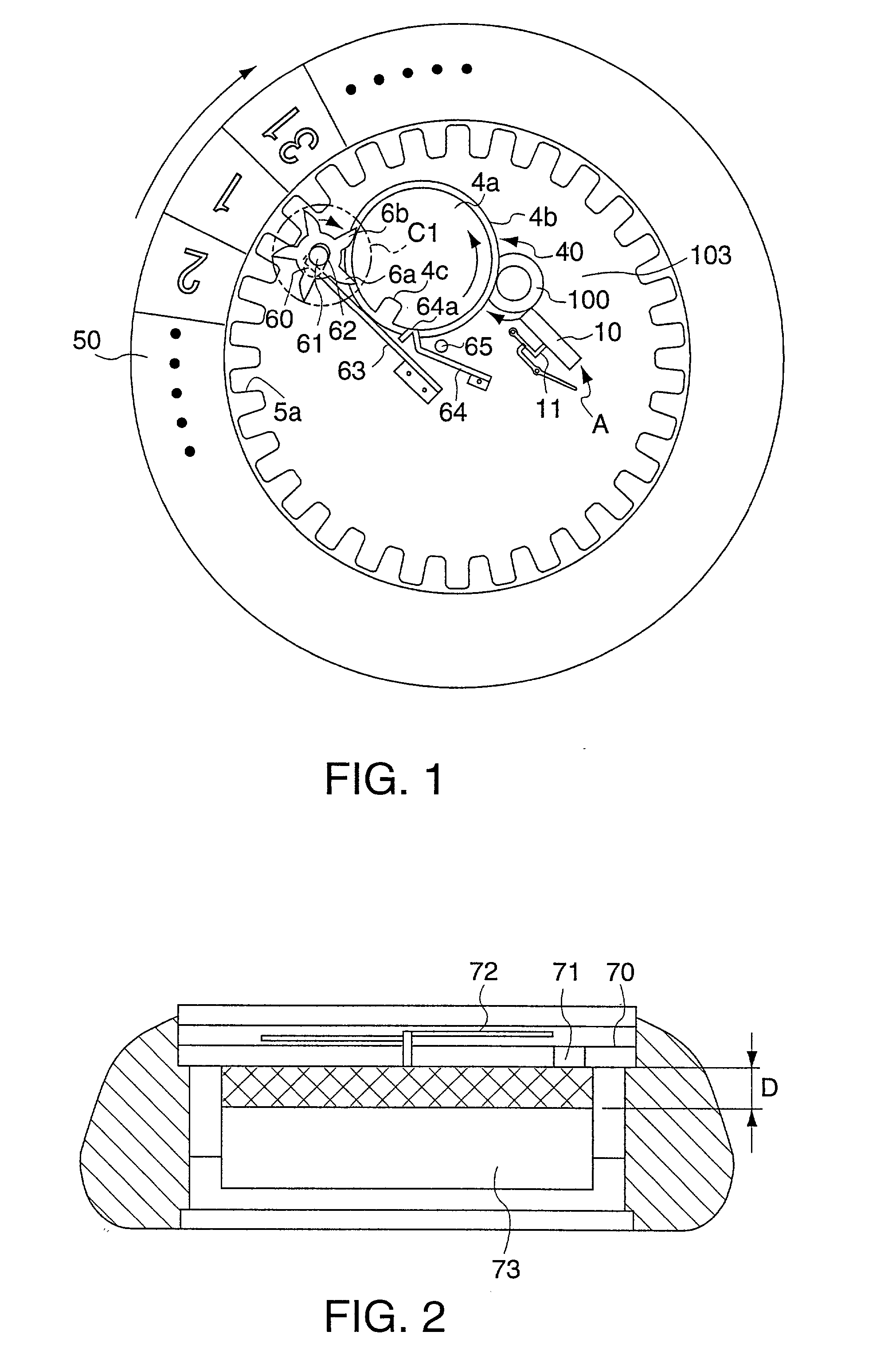
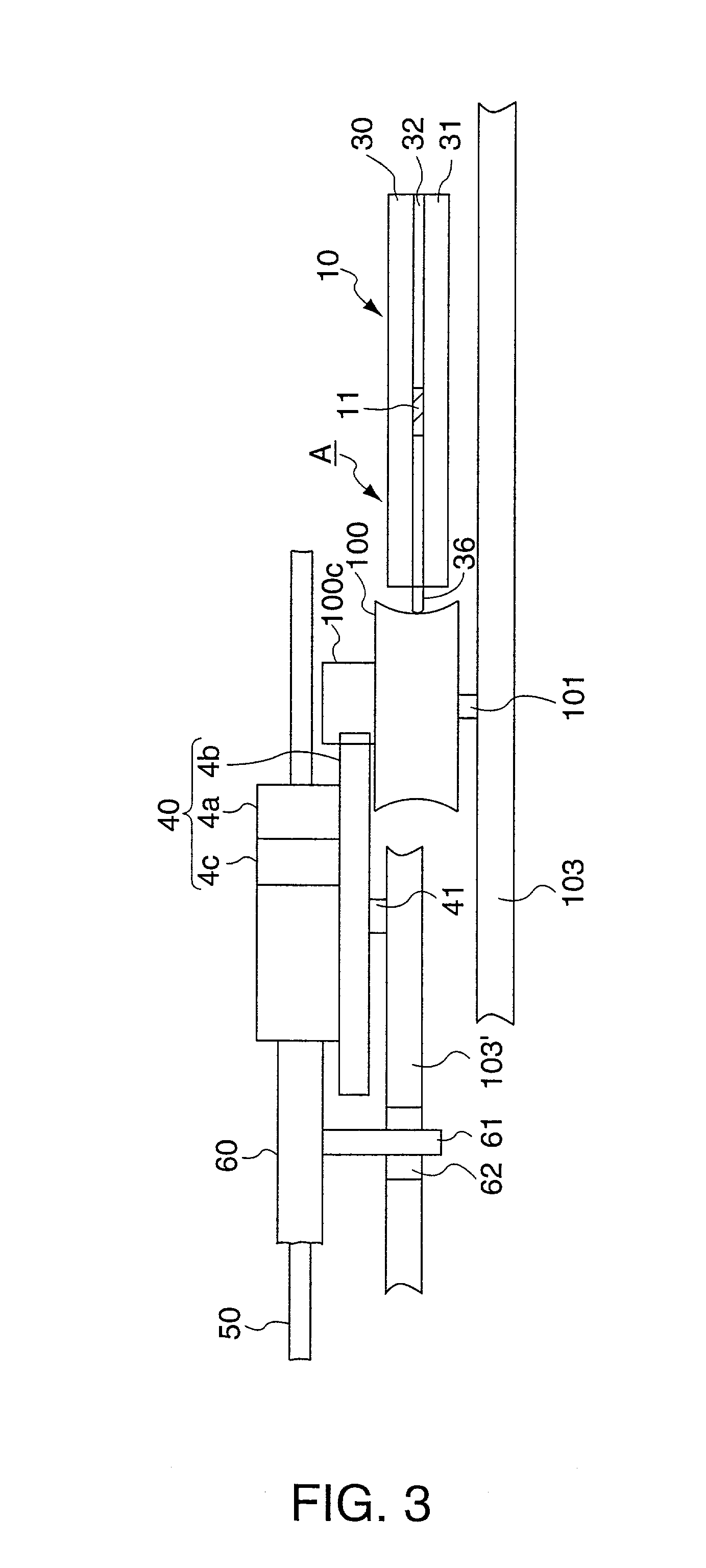
[0074] FIG. 1 is a plan view showing the configuration of a wristwatch calendar display mechanism in which a piezoactuator A according to a first embodiment of this invention is assembled.

[0075] As shown in FIG. 1, the main part of the calendar display mechanism is substantially configured with a piezoactuator A according to the present embodiment, rotor 100 rotationally driven by this piezoactuator A, a speed-reducing wheel train for speed reducing and transferring rotation of the rotor 100, and a date counter 50 rotated by drive force transferred through the speed-reducing wheel train. The speed-reducing wheel train includes a date-turning middle wheel 40 and date-turning wheel 60. The piezoactuator A has a flat rectangular diaphragm 10; this diaphragm 10 is disposed with the end thereof in contact with the outside surface of the rotor 100.

[0076] FIG. 2 is a section view of the watch shown in FIG. 1. The calendar display mec...

embodiment 2

[0127] [2] Embodiment 2

[0128] This embodiment and the first embodiment described above differ only in the configuration of the drive circuit, and the other parts are therefore described with reference to the same figures as the first embodiment.

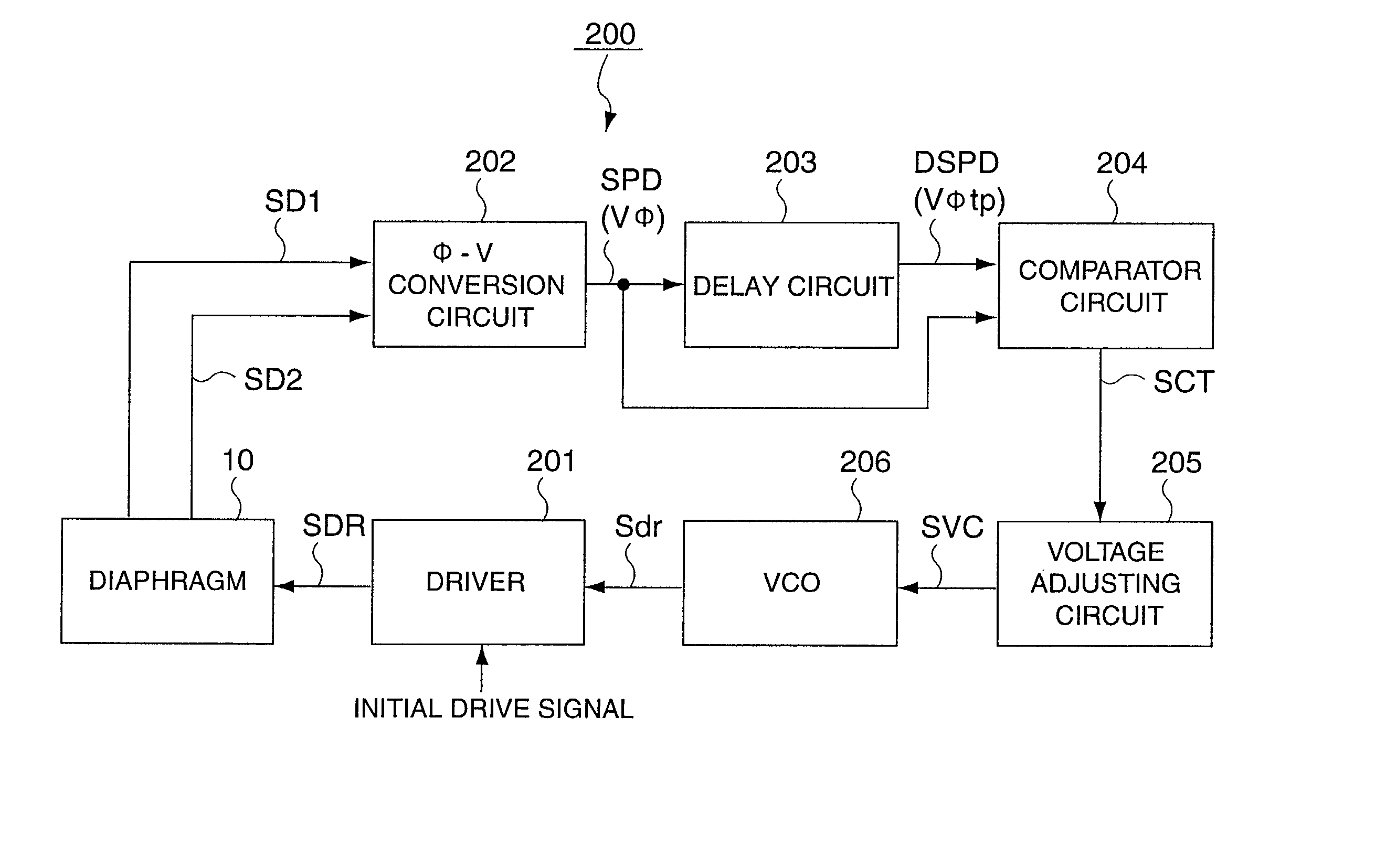
[0129] FIG. 24 is a block diagram showing the configuration of a drive circuit 200A according to the present embodiment of the invention. This drive circuit 200A does not have a delay circuit 203 such as used in the drive circuit 200 of the first embodiment. The drive circuit 200A instead has a constant voltage circuit 210. This constant voltage circuit 210 outputs reference voltage SREF to comparator circuit 204A. This reference voltage SREF is a voltage of the same level as the voltage output from .phi.-V conversion circuit 202 when the phase difference .phi. of detection signals SD1 and SD2 obtained from diaphragm 10 is reference phase difference .phi.d. This reference phase difference .phi.d is a phase difference slightly lower than the m...

embodiment 3

[0135] [3] Embodiment 3

[0136] In the second embodiment described above the frequency of drive voltage signal SDR is controlled so that the phase difference of detection signals SD1 and SD2 obtained from diaphragm 10 goes to reference phase difference .phi.d. In order to efficiently drive the rotor 100 with such frequency control, reference phase difference .phi.d must be set as high as possible within a range not exceeding the maximum phase difference of detection signals SD1 and SD2 obtained from diaphragm 10. However, the maximum phase difference of detection signals SD1 and SD2 differs with individual piezoactuators and even with load and temperature. FIG. 26 shows the frequency characteristic of drive efficiency and the phase difference of detection signals SD1 and SD2 at a temperature of 25.degree. C., and FIG. 27 shows the same frequency characteristic at a temperature of 60.degree. C. If the reference phase difference .phi.d is set to 60.degree., the frequency of drive voltag...


PUM


Abstract

A piezoactuator has a diaphragm, and the diaphragm has flat piezoelectric elements that oscillate in a longitudinal oscillation mode and a sinusoidal oscillation mode. A first electrode for detecting oscillation in the longitudinal oscillation mode, and a second electrode for detecting the amplitude of oscillation in the sinusoidal oscillation mode, are disposed on the surface of the diaphragm. When the piezoactuator is driven with a drive signal, the phase difference of a first detection signal output from the first electrode and a second detection signal output from the second electrode is detected. The frequency at which the detected phase difference becomes the maximum phase difference is then obtained, and a drive signal of a matching frequency is applied to the piezoelectric elements.

Description

[0001] The present invention relates to a piezoelectric actuator having a piezoelectric device and to a drive circuit for the same.RELATED ART[0002] Piezoelectric devices feature outstanding response and efficiency converting electrical energy to mechanical energy. As a result, various types of piezoelectric actuators that use the piezoelectric effect of piezoelectric devices have been developed in recent years. These piezoactuators are used in such fields as piezoelectric buzzers, inkjet heads for printers, and ultrasonic motors. Using piezoactuators in the calendar display mechanism in wristwatches and other such applications where there is strong demand for size reductions has also been investigated in recent years.[0003] Wristwatch calendar display mechanisms to now are generally configured to drive the date counter by indirectly transferring rotational drive power from an electromagnetic stepping motor to the date counter and such through the wheel train of the movement. Wristw...

Claims


Application Information

Patent Timeline
IPC IPC(8): H01L41/04H01L41/09H02N2/00
CPCH02N2/004H02N2/103H02N2/062H02N2/008
Inventor AKAHANE, HIDEHIROSAWADA, AKIHIROFURUHATA, MAKOTO
Owner SEIKO EPSON CORP
Why Eureka
Try Eureka