Method and device for controlling an internal combustion engine

a technology of internal combustion engine and control device, which is applied in the direction of electrical control, process and machine control, instruments, etc., can solve the problems of large number of sensors and different variables that are necessary for detecting different variables, and different variables can only be acquired

Inactive Publication Date: 2002-12-05
ROBERT BOSCH GMBH
View PDF0 Cites 17 Cited by
  • Summary
  • Abstract
  • Description
  • Claims
  • Application Information

AI Technical Summary

Problems solved by technology

Problematical in this device is that different variables needed for the calculation can only be acquired with difficulty using sensors.
Therefore, it is disadvantageous that a large number of sensors are necessary for detecting the different variables.

Method used


Image

  • Method and device for controlling an internal combustion engine
  • Method and device for controlling an internal combustion engine
  • Method and device for controlling an internal combustion engine

Examples


Embodiment Construction

[0009] In the following, the procedure of the present invention is described using a diesel internal combustion engine as an example. However, the invention is not restricted to use in diesel internal combustion engines; it can also be used for other internal combustion engines, particularly for direct-injection gasoline internal combustion engines.

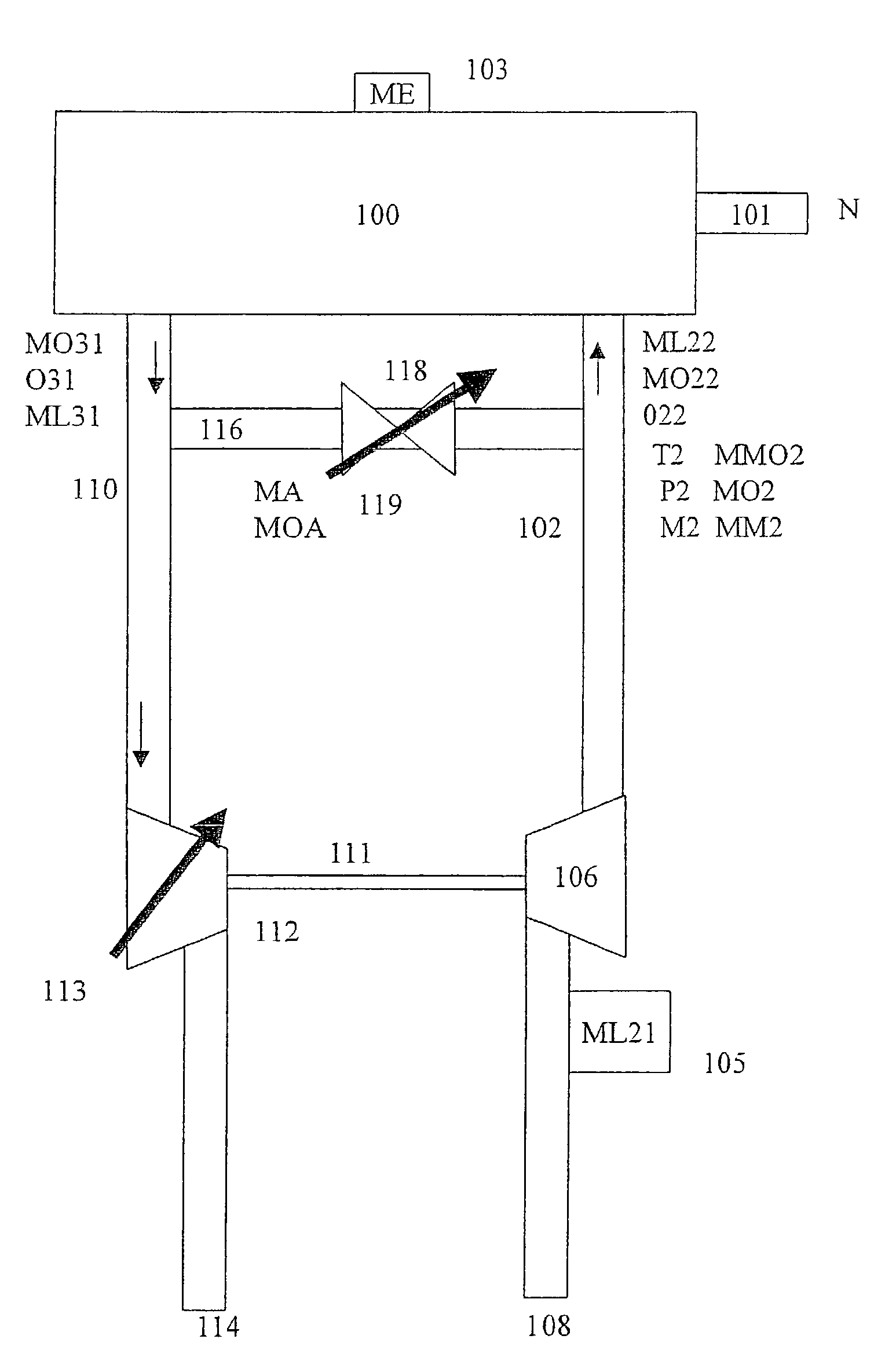
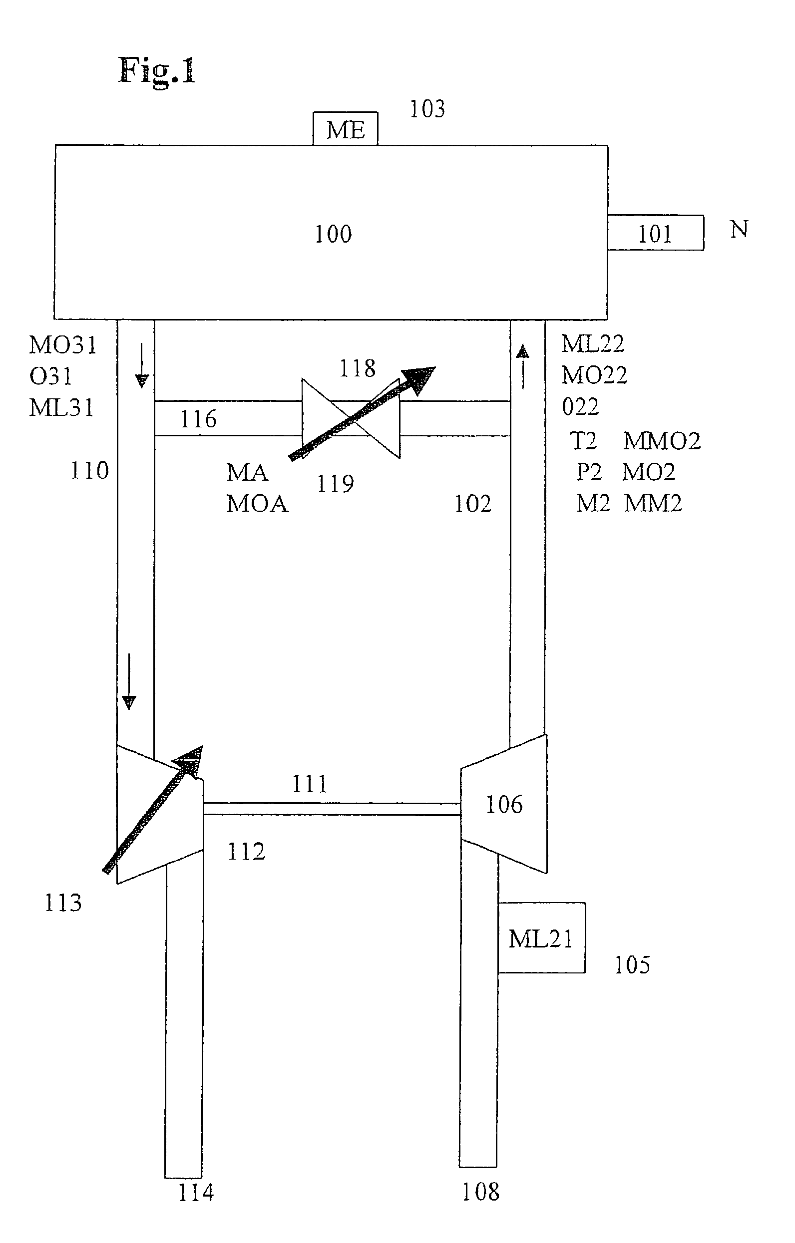
[0010] A certain air quantity ML22 containing a specific oxygen portion MO22 is supplied to an internal combustion engine 100 via a high-pressure fresh-air line 102. The variable MO22 is also designated as the oxygen portion prior to combustion. The air in high-pressure fresh-air line 102 has a temperature T2 and a pressure P2.

[0011] The ambient air arrives at an air compressor 106 via a low-pressure fresh-air line 108, and flows into high-pressure fresh-air line 102. High-pressure fresh-air line 102 is also designated as intake manifold. Air quantity ML21 having oxygen portion MO21 flows via the air compressor into high-pressure fresh-ai...


PUM


Abstract

A method and a device are described for controlling an internal combustion engine. Using at least one model, an oxygen quantity (MO22) flowing into the internal combustion engine is determined on the basis of at least one manipulated variable and at least one measured variable which characterizes the condition of the air in an intake manifold. The oxygen quantity (MO22) is determined on the basis of at least one temperature variable (T2), one pressure variable (P2), one speed variable (N), one fuel-quantity variable (ME) and one air variable (ML21).

Description

BACKGROUND INFORMATION[0001] The present invention relates to a method and a device for controlling an internal combustion engine.[0002] A method and a device for controlling an internal combustion engine are known, for example, from the German Patent 197 56 619. There, a system is described for operating an internal combustion engine, particularly in a motor vehicle, in which the air is supplied to a combustion chamber via a throttle valve arranged in an intake manifold, the quantity flow via the throttle valve being determined. At the same time, a valve is disposed in an exhaust-gas recirculation line, the quantity flow via the valve in the exhaust-gas recirculation line likewise being determined. The air-quantity flow into the combustion chamber is determined on the basis of the two air-quantity flows. Problematical in this device is that different variables needed for the calculation can only be acquired with difficulty using sensors. Therefore, it is disadvantageous that a larg...

Claims


Application Information

Patent Timeline
Patent Type & Authority Applications(United States)
IPC IPC(8): F02D45/00F02D41/00F02D41/14F02D41/18
CPCF02D41/0072F02D41/1401Y02T10/47F02D2041/1433F02D2200/0402F02D41/18Y02T10/40
Inventor ENGEL, GERHARDMEIER, FRANKBLEILE, THOMASRUPP, PETERKRAEMER, WOLFGANG
Owner ROBERT BOSCH GMBH
Why Eureka
Try Eureka