
Fuel injection valve

Inactive Publication Date: 2002-12-05
ROBERT BOSCH GMBH
View PDF3 Cites 16 Cited by
  • Summary
  • Abstract
  • Description
  • Claims
  • Application Information

AI Technical Summary

Benefits of technology

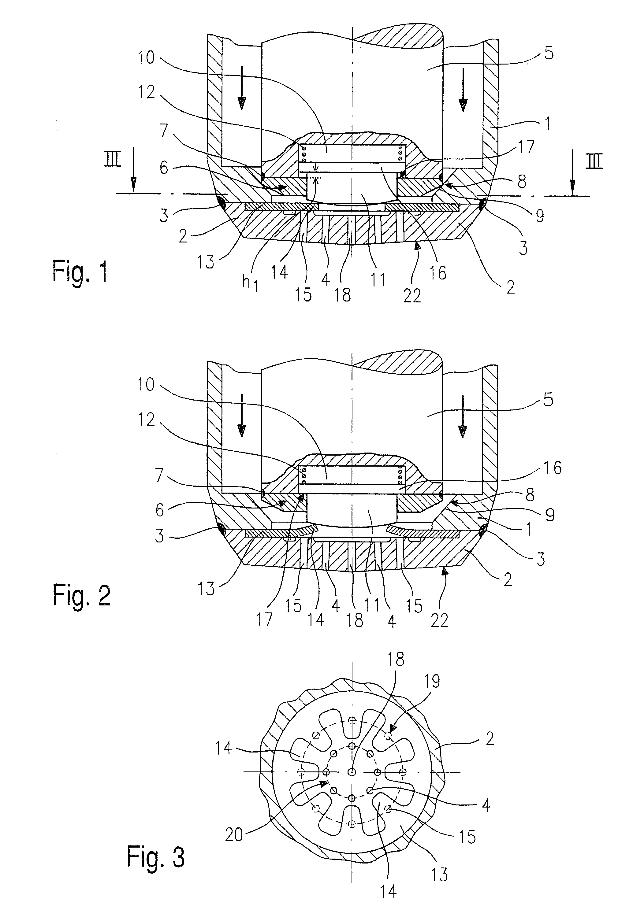
[0005] The fuel injector according to the present invention having the characterizing features of claim 1 has the advantage over the related art due to the fact that it provides a solution for sequentially opening groups of injection orifices in a manner that is inexpensive and easily manufacturable, since the additional group of injection orifices does not require an additional sealing seat manufactured with a high degree of precision in order to be able to open separately.[0006] In particular, the angle over which the fuel is distributed in the fuel injector's jet pattern is adjustable as a function of the valve lift.[0007] Advantageous improvements and developments of the fuel injector described in claim 1 are possible with the measures indicated in the subordinate claims.[0008] A first circle of injection orifices may be covered advantageously by tongues in the disc spring. Further injection orifices may have different injection angles in particular and may be offset with respect to one another by a circumferential angle. In such a case, initially when the injected volume and the load on the internal combustion engine are low, only a certain number of injection orifices having a narrow injection angle may advantageously be opened, so that a fuel injection jet is formed that is made up of fuel jets from those injection orifices having an overall narrow injection angle. As the load on the combustion engine increases and the demand on the stratified charge operation of a combustion engine running according to the lean-burn concept rises correspondingly, the injection orifices of the additional orifice circle are also opened. These may be arranged over a larger injection angle. The fuel injection jet that is injected overall is delivered over a larger angle.

Problems solved by technology

However, the construction is made up of multiple parts and two sealing seats must be manufactured to precise specifications, which gives rise to high costs.
The disadvantage of this arrangement is that in all three sealing seats must be produced to exact specifications.
The disadvantage of this arrangement is that the production of the hollow needle is highly labor-intensive since it also has injection orifices, so that two functions, are combined in a single component, each requiring that the component be produced to a high degree of precision.

Method used


Image

  • Fuel injection valve
  • Fuel injection valve

Examples


Embodiment Construction

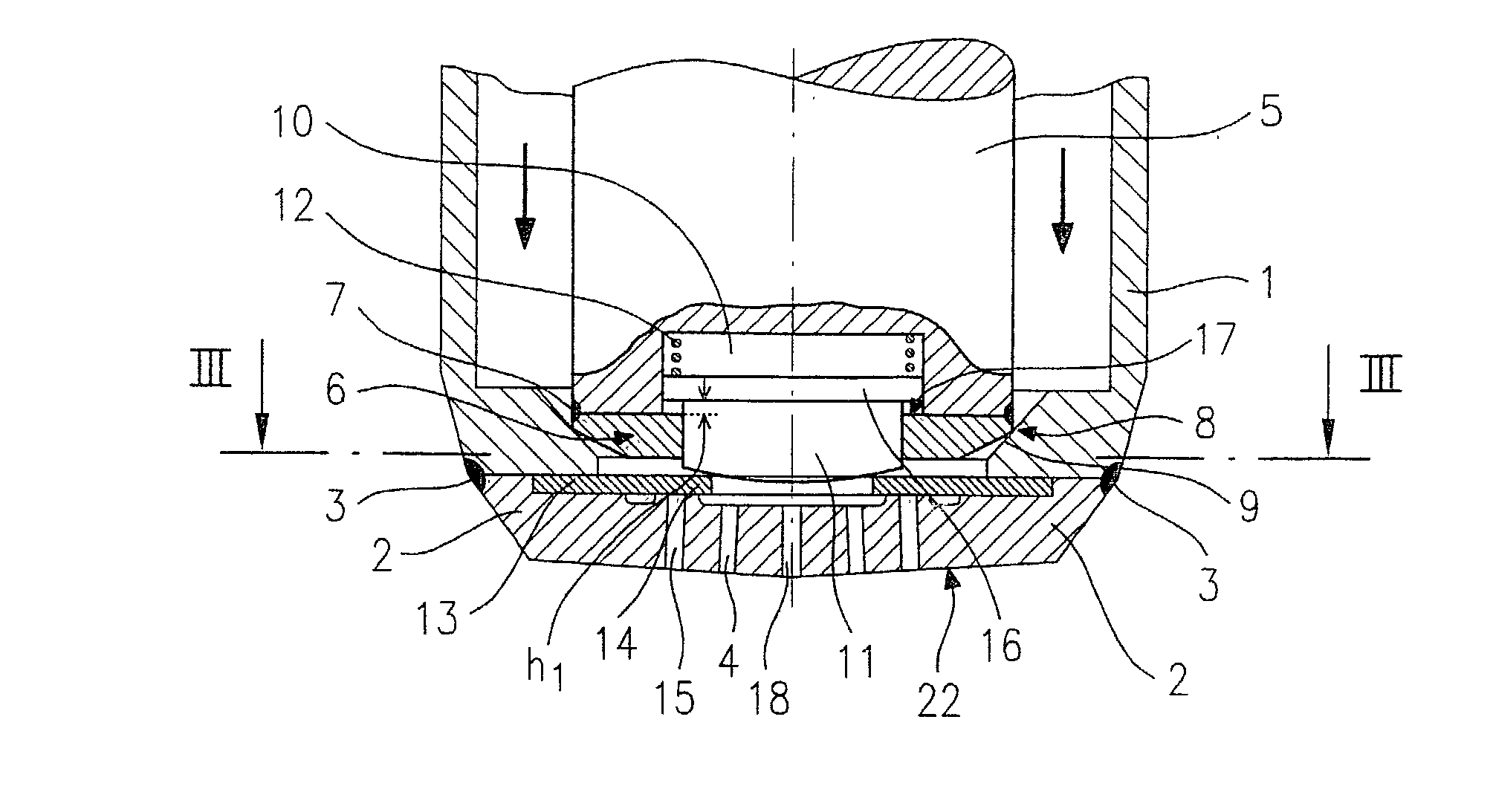
[0013] FIG. 1 shows a section through a portion of an injector according to the present invention which faces the combustion chamber (not illustrated) of an internal combustion engine.

[0014] A valve body 1 is connected by welded seam 3 to injection orifice plate 2 having injection orifices 4, and together they form valve seat body 22. The extremity of valve needle 5 facing the combustion chamber (not shown) is furnished with valve-closure member 6. This valve-closure member 6 is connected to valve needle 5 via welded seam 7. Valve-closure member 6 cooperates with valve seat surface 8 having, for example, a truncated conical shape, provided in valve body 1 to form sealing seat 9. A pressure element 11 is located in an interior recess 10 in valve needle 5, and is pressed against valve needle 5 via a spring 12. Pressure element 11, which in this embodiment has the form of a stepped cylinder, presses on a spring element, here disc spring 13, which has a plurality of tongues 14 extending...


PUM


Abstract

A fuel injector, in particular an injector for fuel injection devices in internal combustion engines has a valve needle (5) with a valve-closure member (6) which cooperates with a valve seat surface (8) in a valve seat body (22) to form a sealing seat (9), in which the valve seat body (22) has a plurality of injection orifices (4, 15, 18) that are isolated from the fuel supply by sealing seat (9). The valve-closure member (6) has a pressure element (11) in a recess (10) facing the valve seat body (22), which is pre-tensioned against the valve seat body (22) by a spring (12) which is supported on the valve-closure member (6) and presses a disc spring (13) against the valve seat body (22), in such manner that the disc spring (13) covers at least one of the injection orifices (15), and the spring element (13) uncovers this injection orifice (15) when the tension exerted by the pressure element (11) is removed.

Description

BACKGROUND INFORMATION[0001] The present invention relates to a fuel injector according to the definition of the species of the main claim.[0002] German Patent Application 32 28 079 Al describes a fuel injector having two valve needles with which it is capable of controlling multiple injection orifices individually. Each valve needle is pre-tensioned against a respective sealing seat by a spring. If one needle is raised out of its sealing seat by a certain clearance, it strikes against a stop of the other valve needle and takes the second valve needle with it as the travel progresses. The two sealing seats of the two valve needles close different injection orifices, which may be directed at differing angles. However, the construction is made up of multiple parts and two sealing seats must be manufactured to precise specifications, which gives rise to high costs.[0003] German Patent Application 30 48 304 Al describes a fuel injector for internal combustion engines having a valve need...

Claims


Application Information

Patent Timeline
IPC IPC(8): F02M45/08F02M51/06F02M61/04F02M61/10F02M61/18
CPCF02M45/086F02M61/1853F02M61/047F02M45/08
Inventor YILDIRIM, FEVZIHOHL, GUENTHERHUEBEL, MICHAELKEIM, NORBERT
Owner ROBERT BOSCH GMBH
Learn More