Dispersion-managed cable for raman-assisted transmission

a technology of raman-assisted transmission and dispersion management, which is applied in multiplex communication, manufacturing tools, instruments, etc., can solve the problems of snr degradation, rapid growth of noise, and signal to noise ratio (snr) degradation at the receiving nod

Inactive Publication Date: 2002-12-05
CORNING INC
View PDF15 Cites 23 Cited by
  • Summary
  • Abstract
  • Description
  • Claims
  • Application Information

AI Technical Summary

Problems solved by technology

Specifically, long-haul optical signal amplification presently suffers from amplification of noise along with the optical signal, resulting in a degraded signal to noise ratio (SNR) at the receiving node.
The above mentioned noise degradation is particularly a problem in small A.sub.eff fiber such as NDNS fiber, primarily because most of the Raman gain occurs in the NDNS section of the long-haul optical transmission system.
This leads to rapid growth of noise with increasing Raman gain.
In addition, at higher Raman gain, the total amplified signal power at the fiber section output becomes comparable to that of the pump and causes depletion.

Method used


Image

  • Dispersion-managed cable for raman-assisted transmission
  • Dispersion-managed cable for raman-assisted transmission
  • Dispersion-managed cable for raman-assisted transmission

Examples


first embodiment

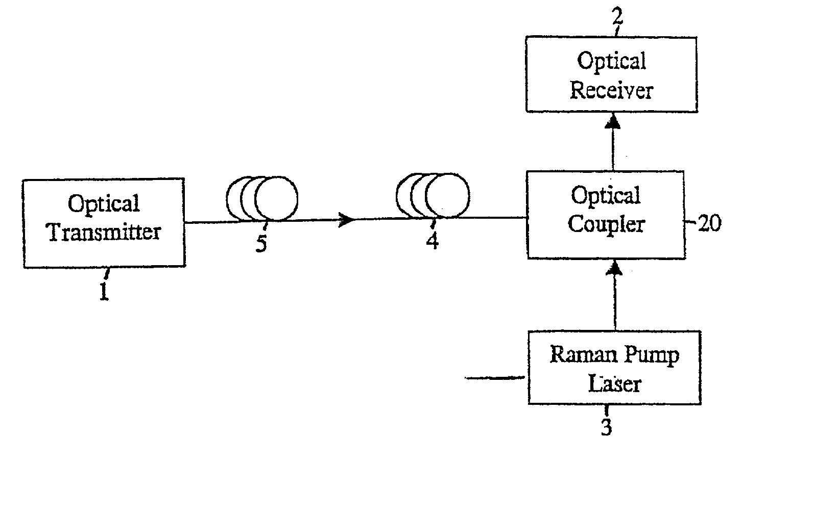
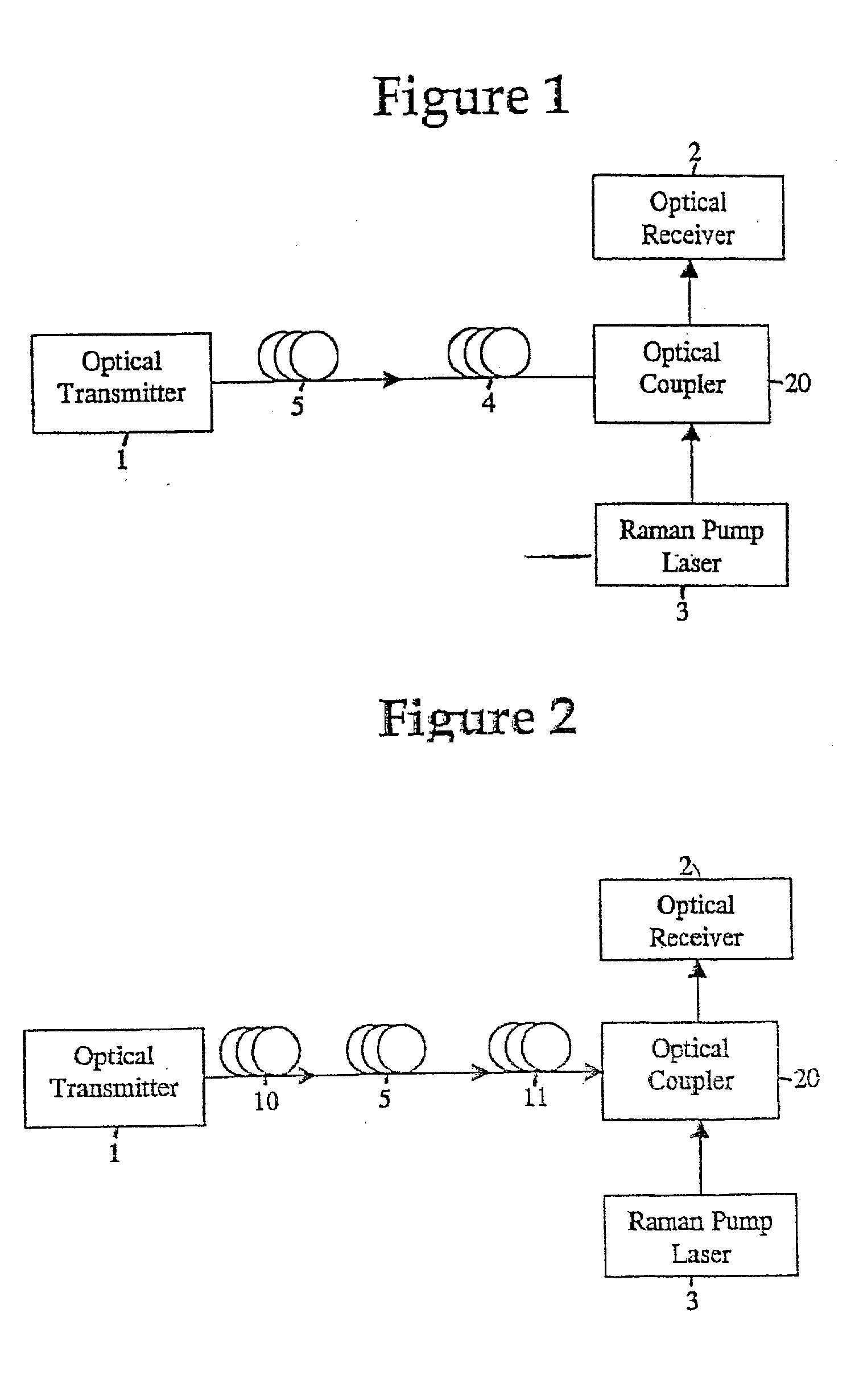
[0048] an apparatus for transmitting an optical signal is shown by the block diagram of FIG. 1. The apparatus includes an optical transmitter 1 that generates an input optical signal to be transmitted from an input end to an output end of an optical fiber. An optical coupler 20 optically couples an optical receiver 2 and a pump light emitting device, preberably a Raman pump laser 3, to the output end of the optical fiber.

[0049] The term ".alpha.-profile" or alpha profile of an optical fiber refers to a refractive index profile, expressed in terms of .DELTA.(r) %, where r is radius, which follows the equation,

.DELTA.(r) %=.DELTA.(r.sub.o)(1-[.linevert split.r-r.sub.o.linevert split. / (r.sub.1-r.sub.o)].sup..alpha.),

[0050] where r.sub.o is the point at which .DELTA.(r) % is maximum, r.sub.1 is the point at which .DELTA.(r) % is zero, and r is in the range r.sub.i.ltoreq.r.ltoreq.r.sub.f, where delta is defined above, r.sub.i is the initial point of the .alpha.-profile, r.sub.f is the f...

third embodiment

[0068] an apparatus for transmitting an optical signal comprises a first section of optical fiber, preferably a PDPS fiber, which preferably has a local dispersion of at least 10 ps / nm. Preferably, the first section of optical fiber has an A.sub.eff of at least 80 .mu.m.sup.2. The second section of optical fiber preferably comprises NDNS fiber, preferably having an A.sub.eff less than 30 .mu.m.sup.2. The third section of optical fiber preferably comprises optical fiber with an A.sub.eff less than that of the PDPS optical fiber section and greater than that of the NDNS optical fiber section. Preferably, the third section of optical fiber has an A.sub.eff in the range of 30 .mu.m.sup.2 to 80 .mu.m.sup.2.

[0069] The aforementioned advantages of the first embodiment also apply to this third embodiment. The use of PDPS fiber and NDNS fiber partially compensates for dispersion in the optical fiber along the optical transmission path and provides amplification earlier in the transmission pa...


PUM

PropertyMeasurementUnit
lengthaaaaaaaaaa
lengthaaaaaaaaaa
areaaaaaaaaaaa

Abstract

An apparatus for transporting an optical signal is provided. The apparatus includes sections of optical fiber span with at least one section negative dispersion, negative slope fiber positioned at a distance from the output. A pump light emitting device optically coupled to the optical fiber span near the output is provided for generating an amplification signal.

Description

[0001] The present application claims priority to and the benefit of U.S. Provisional Patent Application Serial No. 60 / 276,108 filed Mar. 16, 2001, U.S. Provisional Patent Application Serial No. 60 / 298,257 filed Jun. 14, 2001, U.S. Provisional Patent Application Serial No. 60 / 328,279 filed Oct. 9, 2001, U.S. Provisional Patent Application Serial No. 60 / 328,550 filed Oct. 10, 2001, and U.S. Provisional Patent Application Serial No. 60 / 339,864 filed Oct. 30, 2001. The foregoing provisional applications are incorporated by reference herein in their entirety.[0002] 1. Field of the Invention[0003] The invention relates generally to long-haul optical fiber networks, more particularly, to long-haul spans comprising dispersion managed optical fiber with signal amplification.[0004] 2. Background of the Invention[0005] Signal degradation encountered when transmitting optical signals over long-haul optical fiber has greatly increased the need for improved optical signal amplification devices a...

Claims


Application Information

Patent Timeline
Patent Type & Authority Applications(United States)
IPC IPC(8): C03B37/014G02B6/34G02B6/036G02F1/35H01S3/10H01S3/30H04B10/02H04B10/18
CPCC03B37/01446C03B2201/04G02B6/02019G02B6/02261H04B10/25253G02B6/0285G02B6/03677G02B6/29377G02B6/0228Y02P40/57G02B6/00
Inventor BICKHAM, SCOTT R.DALGOUTTE, DAVID G.GROCHOCINSKI, JAMES M.VASILYEV, MICHAEL
Owner CORNING INC
Why Eureka
Try Eureka