Gas generator for air bag and air bag device

a gas generator and air bag technology, applied in the direction of pedestrian/occupant safety arrangement, vehicular safety arrangments, vehicle components, etc., can solve the problems of difficulty in closing, difficulty in supplying gas generators capable of easily and reliably closing the gas discharging port, and inability to provide gas generators

Inactive Publication Date: 2002-12-19
DAICEL CHEM IND LTD
View PDF11 Cites 18 Cited by
  • Summary
  • Abstract
  • Description
  • Claims
  • Application Information

AI Technical Summary

Problems solved by technology

Therefore, it is difficult to close the gas discharging port using the seal tape, and especially when the housing is long in the axial direction, it is difficult to close the gas discharging port with the seal tape unless any contrivance is made.
However, a gas generator capable of easily and reliably closing the gas discharging port has not been provided heretofore.
However, since the ignition means having high output is relatively expensive, such an ignition means is not preferable in view of reduction of a producing cost of the gas generator.
However, in such a gas generator, if a structure for sealing the gas generating agent stored in the combustion chamber is provided in the respective chambers, the internal structure is complicated, a size of a container becomes large, and a cost therefor becomes expensive.
And if the ports are formed in a gas discharging port line or a gas discharging port group arranged along the axial direction of the housing, the ports can be easily and unfailingly closed with the seal tape.
However, the partitioning m

Method used


Image

  • Gas generator for air bag and air bag device
  • Gas generator for air bag and air bag device
  • Gas generator for air bag and air bag device

Examples


embodiment 1

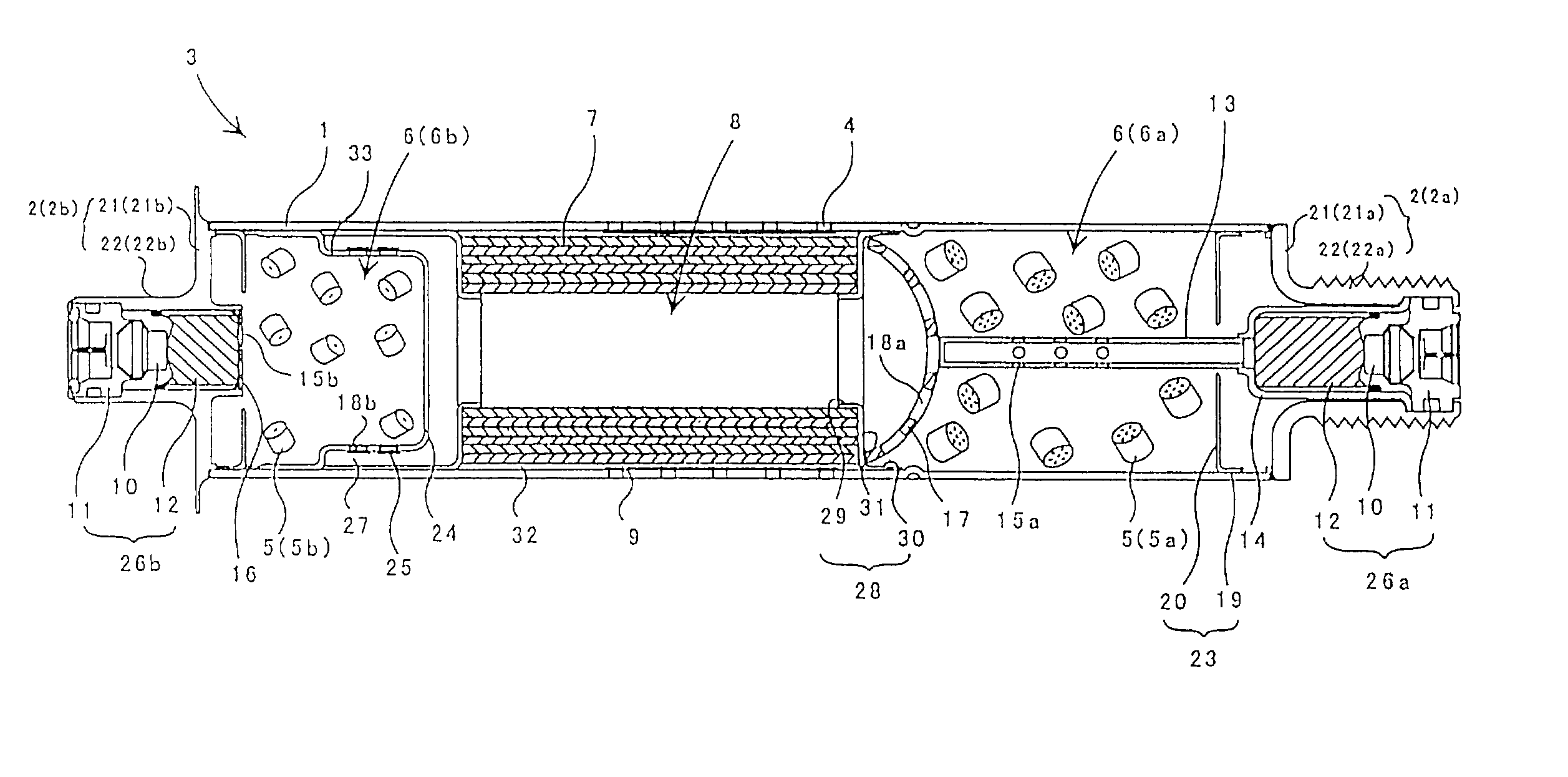
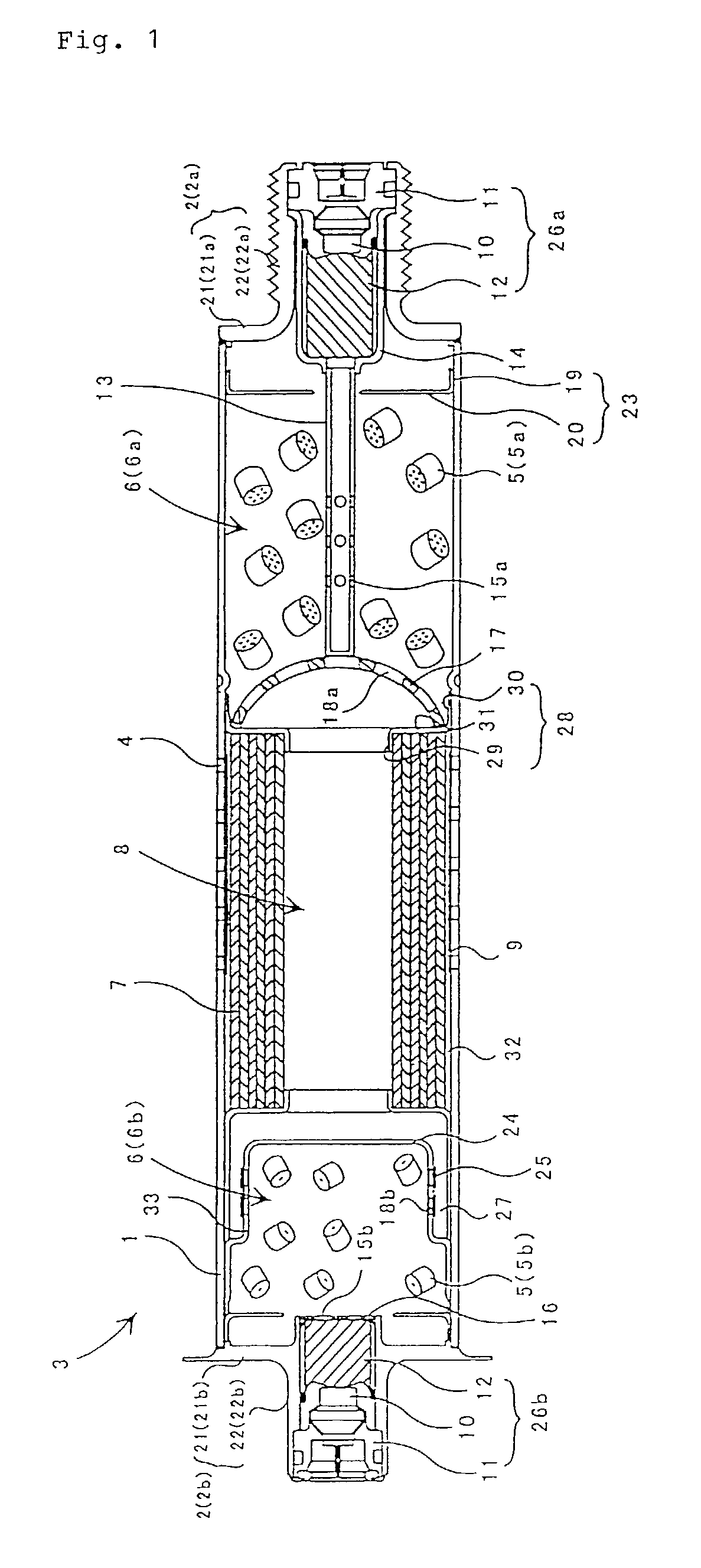
[0082] FIG. 1 is a vertical cross sectional view of a first embodiment of a gas generator for an air bag according to the present invention.

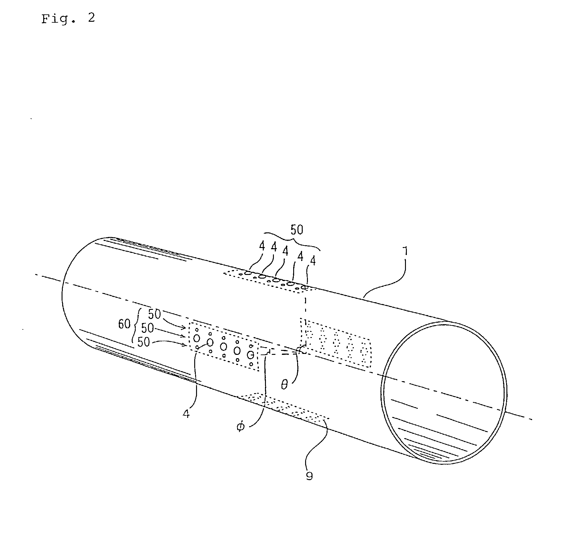
[0083] The gas generator has a housing 3 formed by integrally uniting a cylindrical diffuser shell 1 having a gas discharging port 4 and closure shells 2 which close openings in ends of the diffuser shell 1. A plurality of gas discharging ports are formed in the peripheral wall of the cylindrical housing 3, being arranged along the axial direction of the housing as described below. And in the housing 3, combustion chambers 6 for accommodating gas generating agents 5 as gas generating means are formed on both sides (i.e., on the closure shells sides) in the axial direction. A filter means accommodating chamber 8 for accommodating a cylindrical filter means 7 is provided between the combustion chambers 6, i.e., in the vicinity of the center of the housing 3. In describing this embodiment, the right side combustion chamber in the drawing is defined...

embodiment 2

[0099] FIG. 5 is a vertical cross sectional view of other embodiment of a gas generator for an air bag according to the present invention.

[0100] This gas generator has a housing 3 formed by integrally uniting a cylindrical diffuser shell 1 having a gas discharging port 4 and a closure shell 40 which closes openings in the ends of the diffuser shell 1 in the same manner as the gas generator shown in FIG. 1. However, the filter means accommodating chamber 8 is disposed in a different place, and the filter means accommodating chamber 8 is defined at the end of the housing 3. One combustion chamber 6 for accommodating the gas generating agent 5 is defined at the other end of the housing 3. Therefore, in this embodiment, the combustion chamber 6 and the filter means accommodating chamber 8 are adjacently provided in the housing 3 in the axial direction.

[0101] The combustion chamber 6 formed at the one end of the housing 3 is separated from the filter means accommodating chamber 8 by a pa...

embodiment 3

[0110] FIG. 6 is a vertical cross sectional view of one embodiment of a gas generator for an air bag according to the present invention. In the gas generator of this embodiment, a combustion chamber and a filter means accommodating chamber are adjacent to and communicate with each other in the axial direction, and a gas generating means in the combustion chamber is supported by a plate member, and a flame-transferring tube projects in the combustion chamber.

[0111] This gas generator has a housing 103 formed by integrally joining a cylindrical diffuser shell 101 having a gas discharging port 104 and a closure shell 102 which closes openings in ends of the diffuser shell 102. In this housing 103, a combustion chamber 105 for accommodating gas generating agents 107 and a filter means accommodating chamber 106 for accommodating a cylindrical filter means 115 are adjacently provided in an axial direction of the housing 103.

[0112] The combustion chamber 105 formed at an end of the housing...


PUM


Abstract

The present invention provides a gas generator capable of easily and unfailingly closing a gas discharging port formed in a housing. The invention provides a gas generator for an air bag in which an amount of accommodated gas generating agent can be varied and the gas generating agent can be ignited and burnt unfailingly even by the ignition means having normal output. The invention provides a gas generator which has sealing structures as little as possible and in addition to a simple structure and can be manufactured easily, and in that a activation performance and activation timing can be adjusted at a multiple stage. The invention provides a gas generator for an air bag comprising, in a housing provided at its peripheral wall with a plurality of gas discharging ports, an ignition means to be actuated upon the impact, and a gas generating means to be ignited and burnt by the ignition means, wherein the gas discharging ports are arranged in the axial direction of the housing to form a gas discharging port line, two to six gas discharging port lines are arranged close to each other in the circumferential direction of the housing to form a gas discharging port group, the gas discharging port groups are arranged in the circumferential direction of the housing at predetermined intervals. The invention provides a gas generator for an air bag comprising, in a cylindrical housing which is longer in the axial direction than in the radial direction, an ignition means to be actuated upon the impact, and a gas generating means to be ignited and burnt by the ignition means, wherein a combustion chamber for accommodating the gas generating means and a filter means accommodating chamber for accommodating a filter means are formed in the housing adjacent to each other in the axial direction so that these cambers communicate with each other, the combustion chamber accommodating the gas generating means is separated from the filter means accommodating chamber by a partitioning member having a through-hole. The invention provides a gas generator for an air bag comprising, in a cylindrical housing which is longer in the axial direction than in the radial direction, two ignition means to be actuated upon the impact, and two combustion chambers accommodating gas generating means to be ignited and burnt by the ignition means, wherein the combustion chambers are provided on the opposite ends in the housing, a filter means accommodating chamber for accommodating a filter means is provided between the combustion chambers, either of the combustion chambers communicates with the filter means accommodating chamber.

Description

[0001] The present invention relates to a gas generator for an air bag suitably used for an inflating type safety system of an automobile, and more particularly, to a gas generator for an air bag characterized in an arrangement of a gas discharging port, a sealing method thereof and an internal structure of a housing, and to an air bag apparatus using such a gas generator.PRIOR ART[0002] An air bag system which is mounted on various kinds of vehicles and the like including automobiles, aims to hold the occupant by means of an air bag (bag body) rapidly inflated by a gas when the vehicle collides at a high speed so as to prevent the occupant from crashing into a hard portion inside the vehicle such as a steering wheel, a windscreen due to an inertia and being injured. This kind of air bag system generally comprises a gas generator which actuates upon a collision of the vehicle and discharges a gas, and an air bag which introduces the gas to inflate.[0003] Therefore, in a gas generato...

Claims


Application Information

Patent Timeline
IPC IPC(8): B60R21/26B60R21/16B60R21/263B60R21/264
CPCB60R21/2644B60R2021/2648B60R2021/2633B60R21/16B60R21/26B60R21/263
Inventor WATASE, TAKEFUMIYABUTA, MIKIO
Owner DAICEL CHEM IND LTD
Why Eureka
Try Eureka