Stamped exhausts manifold for vehicle engines

a technology for exhaust manifolds and vehicle engines, which is applied in the direction of machines/engines, branching pipes, mechanical equipment, etc., can solve the problems of failure of the manifold under extreme operating temperatures, limitations of metal stampings on the and increasing the dictated configuration of the manifold by the vehicle designer

Inactive Publication Date: 2002-12-26
METALDYNE TUBULAR COMPONENTS
View PDF0 Cites 13 Cited by
  • Summary
  • Abstract
  • Description
  • Claims
  • Application Information

AI Technical Summary

Benefits of technology

0008] The present invention overcomes the disadvantages of the prior known manifolds by providing an exhaust manifold w

Problems solved by technology

However, as the engine compartments have been reduced in size and the increased complexity of modern engines has reduced available space, vehicle designers have increasingly dictated complex and compact manifold configurations.
However, the limitations of metal stampings limited the configurations of the manifold since manifold tubes with tight radiuses could not be manufactured.
A small radius exerts stresses on the stamping which can result in failure of the manifold under the extreme operating temperature

Method used


Image

  • Stamped exhausts manifold for vehicle engines
  • Stamped exhausts manifold for vehicle engines
  • Stamped exhausts manifold for vehicle engines

Examples


first embodiment

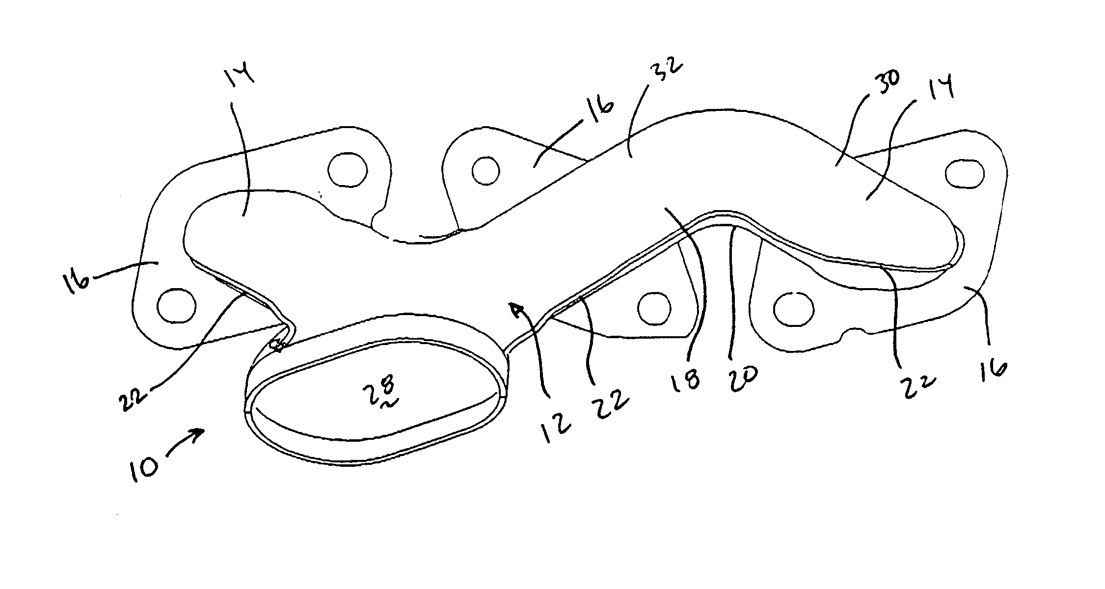
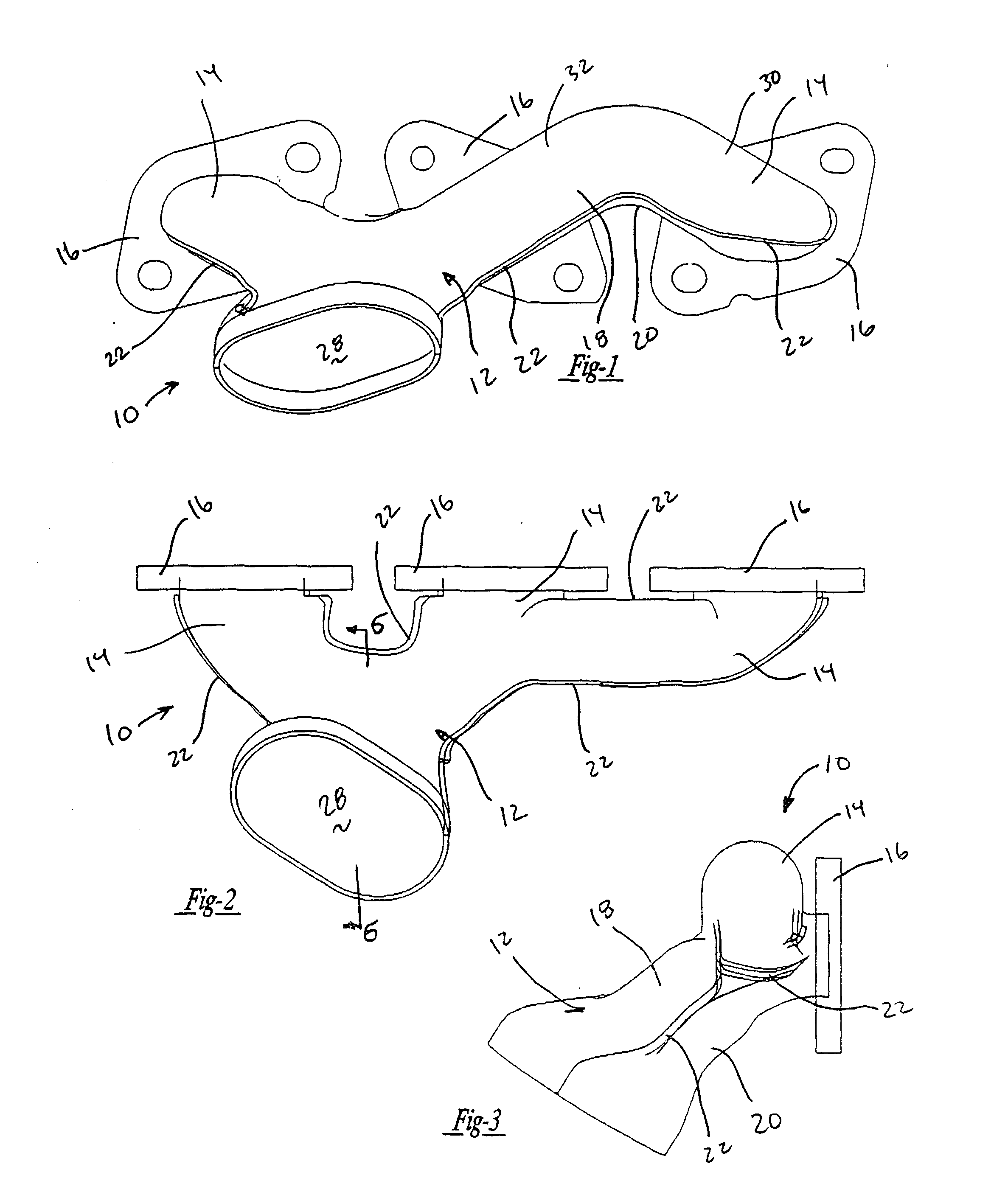
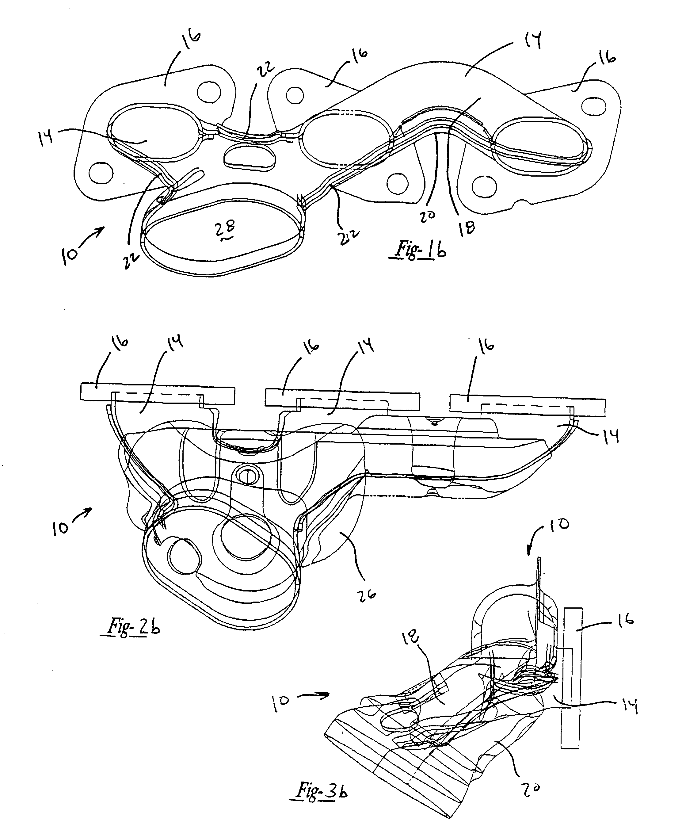
[0029] the exhaust manifold 10 is designed for connection to one side of a vehicle engine (now shown). The manifold 10 has a body 12 comprising a plurality of tubular arms 14 corresponding to the number of exhaust ports. Each of the tubular arms 14 terminates with a mounting flange used to sealingly secure the manifold 10 to the engine in communication with the exhaust port. The body 12 including the arms 14 is manufactured of two stamped halves 18 and 20. The stamped metal halves 18 and 20 are attached along a longitudinal weld seam 22. Preferably, the seam 22 has an overlap as best shown in FIG. 5 to improve the sealing capability of the seam 22. Additional components such as sensors 24 and heat shields 26 may be incorporated as required for a specific application.

[0030] The manifold 10 formed by the two stamped halves 18 and 20 includes a first tube 14 proximate a collector chamber 28, a second tube 14 remote from the chamber 28 and an intermediate tube 14. All of the tubular arm...


PUM


Abstract

An exhaust manifold for a vehicle engine constructed of two stamped halves joined together along a longitudinal weld seam to form a compactly configured manifold. The assembled manifold includes exhaust tubes in communication with the combustion chambers of the engine and a collector chamber for directing exhaust from the tubes to the exhaust system. The individual exhaust tubes are configured for a compact installation and the collection chamber facilitates efficient flow of exhaust through the manifold.

Description

[0001] This application claims the priority of U.S. Provisional Patent Application No. 60 / 127,313 filed on Apr. 1, 1999 and U.S. patent application Ser. No. 09 / 535,320 filed on Mar. 27, 2000.[0002] I. Field of the Invention[0003] This invention relates to exhaust manifolds for vehicle engines and, in particular, to an exhaust manifold assembled from two stamped halves which optimizes the flow of exhaust gases and is capable of fitting within the confined spatial limitations of modem engine assemblies.[0004] II. Description of the Prior Art[0005] Exhaust manifolds are utilized to direct exhaust gases from the outlet ports of the engine combustion chamber to the exhaust system for discharge into the atmosphere. The manifolds typically collect the exhaust gases from a plurality of chambers and direct the gases through a single passageway. In order to facilitate efficient operation of the engine and exhaust of the gases, the configuration of the manifold must facilitate collection and d...

Claims


Application Information

Patent Timeline
IPC IPC(8): F01N13/10F01N13/18F16L41/03
CPCF01N13/10F01N13/102F16L41/03F01N2450/22F01N2470/06F01N13/1872
Inventor KENYON, PAULSTEMPIEN, VINCEKETELHUT, TOM
Owner METALDYNE TUBULAR COMPONENTS
Why Eureka
Try Eureka