Heatsink design for uniform heat dissipation

a heat dissipation and heat sink technology, applied in the field of heat transfer, can solve the problems of chip failure, frequent heat generation of chips, and rare use of pure copper heat sinks

Inactive Publication Date: 2002-12-26
ORACLE INT CORP
View PDF0 Cites 47 Cited by
  • Summary
  • Abstract
  • Description
  • Claims
  • Application Information

AI Technical Summary

Problems solved by technology

When in use, the chips often produce significant levels of heat.
The increased level of heat produced by chips during their use can lead to a number of problems; for example, elevated levels of heat can potentially cause the chip to malfunction.
Copper is a better conductor of heat than aluminum, but a pure copper heatsink is seldom used due to cost and weight constraints.
Some commonly used semiconductor materials, such as glass and glass ceramic composites, have low thermal conductivities and therefore hinder the dissipation of heat.
The commonly used methods of cooling that are mentioned above have sometimes been found to be inadequate for cooling high performance chips.
Current aluminum heatsink designs often cannot dissipate heat from the chip fast enough.
This design attempts to balance the increased heat transfer capabilities of copper with the increased cost associated with its use.
But a flat copper plate often cannot distribute the heat from a localized source evenly across its surface, thereby resulting in a heat concentration, sometimes referred to as a hot spot, at the location of the heat source.
Having the airflow pattern and / or fan position as a critical factor in the ability of a chip to function properly is an undesired limitation on the ability to manufacture and package the chip within an electrical device.

Method used


Image

  • Heatsink design for uniform heat dissipation
  • Heatsink design for uniform heat dissipation
  • Heatsink design for uniform heat dissipation

Examples


Embodiment Construction

[0039] Illustrative embodiments of the invention are described below. In the interest of clarity, not all features of an actual implementation are described in this specification. It will of course be appreciated that in the development of any such actual embodiment, numerous implementation-specific decisions must be made to achieve the developers' specific goals, such as compliance with system-related and business-related constraints, which will vary from one implementation to another. Moreover, it will be appreciated that such a development effort might be complex and time-consuming, but would nevertheless be a routine undertaking for those of ordinary skill in the art having the benefit of this disclosure.

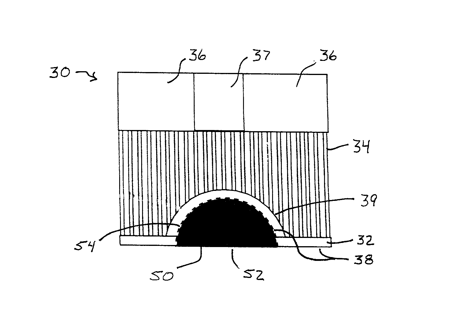
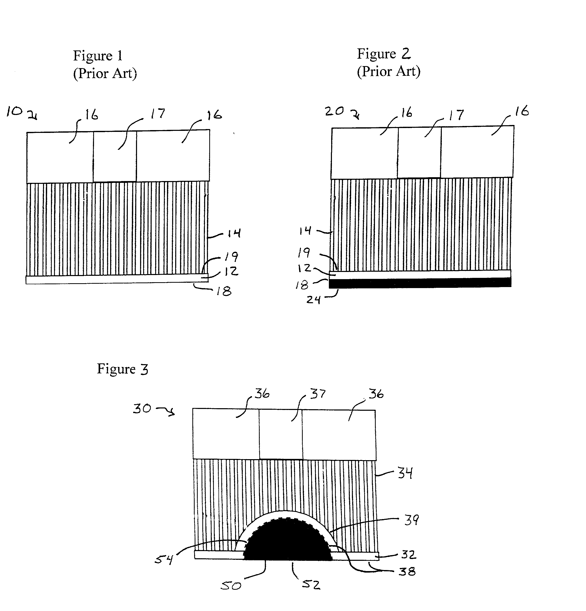
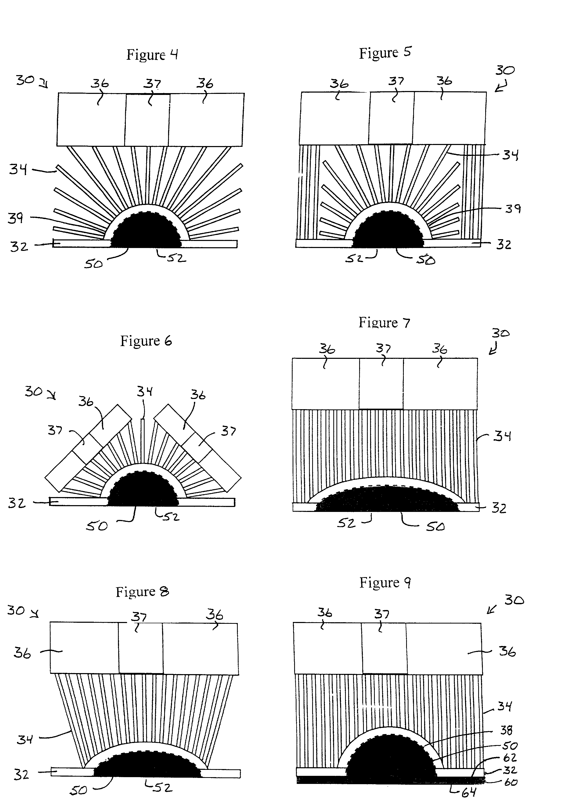
[0040] Referring to the attached drawings, FIG. 1 shows a heatsink 10 comprising a base 12, a plurality of fins 14, a conventional cooling fan 16 and a conventional cooling fan motor 17. Typically the base 12 and fins 14 will be constructed of aluminum. The base 12 has a bottom ...


PUM

PropertyMeasurementUnit
thermal conductivityaaaaaaaaaa
surface areaaaaaaaaaaa
convex curvatureaaaaaaaaaa

Abstract

The present invention discloses improved heatsink designs and methods for cooling a heat source. One embodiment is a heatsink assembly for removing heat from an electronic component, the heatsink assembly comprising a copper-based core section having a first surface generally adapted to conform to an exposed mating surface of an electronic device and a second surface having a generally convex curvature having a greater surface area than the first surface. An aluminum-based outer section has a first surface comprising a concave curvature that is generally adapted to conform to the convex curvature of the core and a second surface. A plurality of fin elements protrude outwardly from the second surface of the outer section. At least one cooling fan can be positioned to direct airflow onto the fin elements. The core section can comprise a semi-spherical shape and can be joined by a finger-joint type connection to the outer section. A key design element of the present invention is the speed in which the heat is transferred away from the heat source. Due to a concentration of material having greater thermal conductivity located near the heat source, heat is allowed to transmit further and faster away from the source than with previous heatsink designs and is distributed more evenly throughout the main heatsink structure.

Description

[0001] 1. Field of the Invention[0002] This invention relates generally to heat transfer, and, more particularly, to heatsink assemblies to remove at least some of the heat produced by a heat source, such as an electronic component.[0003] 2. Description of Related Art[0004] Electronic components such as integrated circuits or semiconductor chips, hereafter referred to as "chips", are well known and commonly used in the art to perform electronic functions. When in use, the chips often produce significant levels of heat. To reduce the heat generated, the chip size needs to be decreased which causes the heat to be concentrated into a smaller area. As technology has increased the capacity of the chips to perform functions, it has been found that the amount of concentrated heat produced has increased significantly. The increased level of heat produced by chips during their use can lead to a number of problems; for example, elevated levels of heat can potentially cause the chip to malfunc...

Claims


Application Information

Patent Timeline
Patent Type & Authority Applications(United States)
IPC IPC(8): F28F3/04H01L23/367H01L23/467
CPCF28F3/04H01L23/367H01L23/467Y10T29/4935H01L2924/0002H01L2924/09701H01L2924/00
Inventor HSIEH, TEH-MINGTRAN, BRYAN H.ALIPIO, JULIAN A.
Owner ORACLE INT CORP
Why Eureka
Try Eureka