Circuit layout for several sensor elements

Inactive Publication Date: 2003-01-02
E G O ELEKTRO GERAETEBAU GMBH
View PDF0 Cites 11 Cited by
  • Summary
  • Abstract
  • Description
  • Claims
  • Application Information

AI Technical Summary

Problems solved by technology

Thus, certain costs are involved with the said circuit lay

Method used


Image

  • Circuit layout for several sensor elements
  • Circuit layout for several sensor elements
  • Circuit layout for several sensor elements

Examples


Embodiment Construction

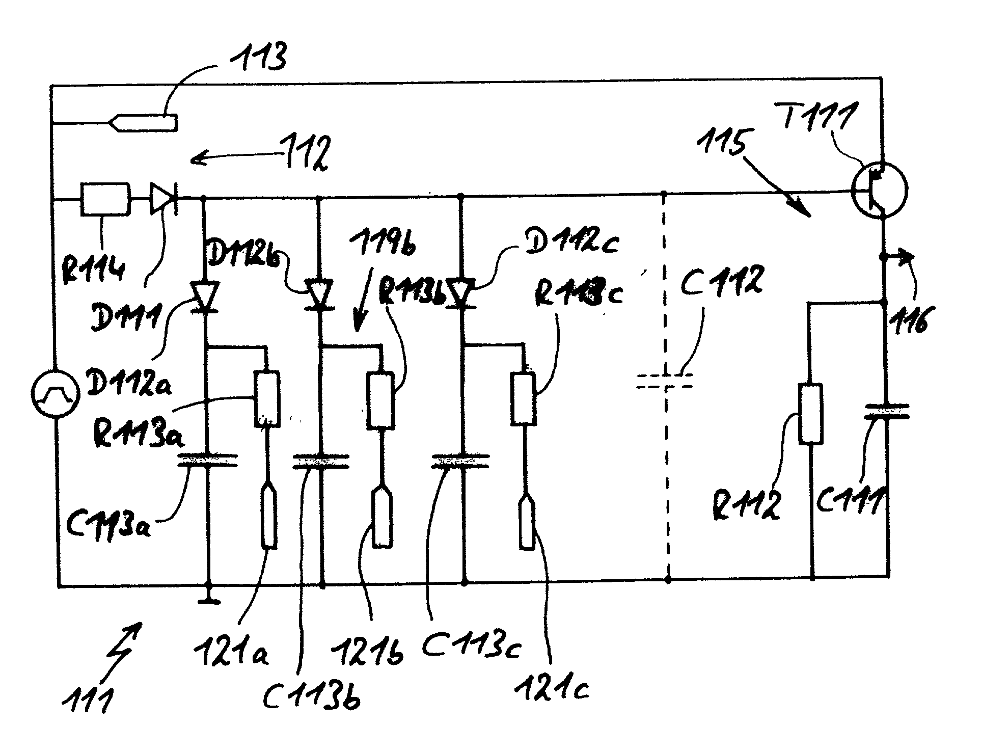
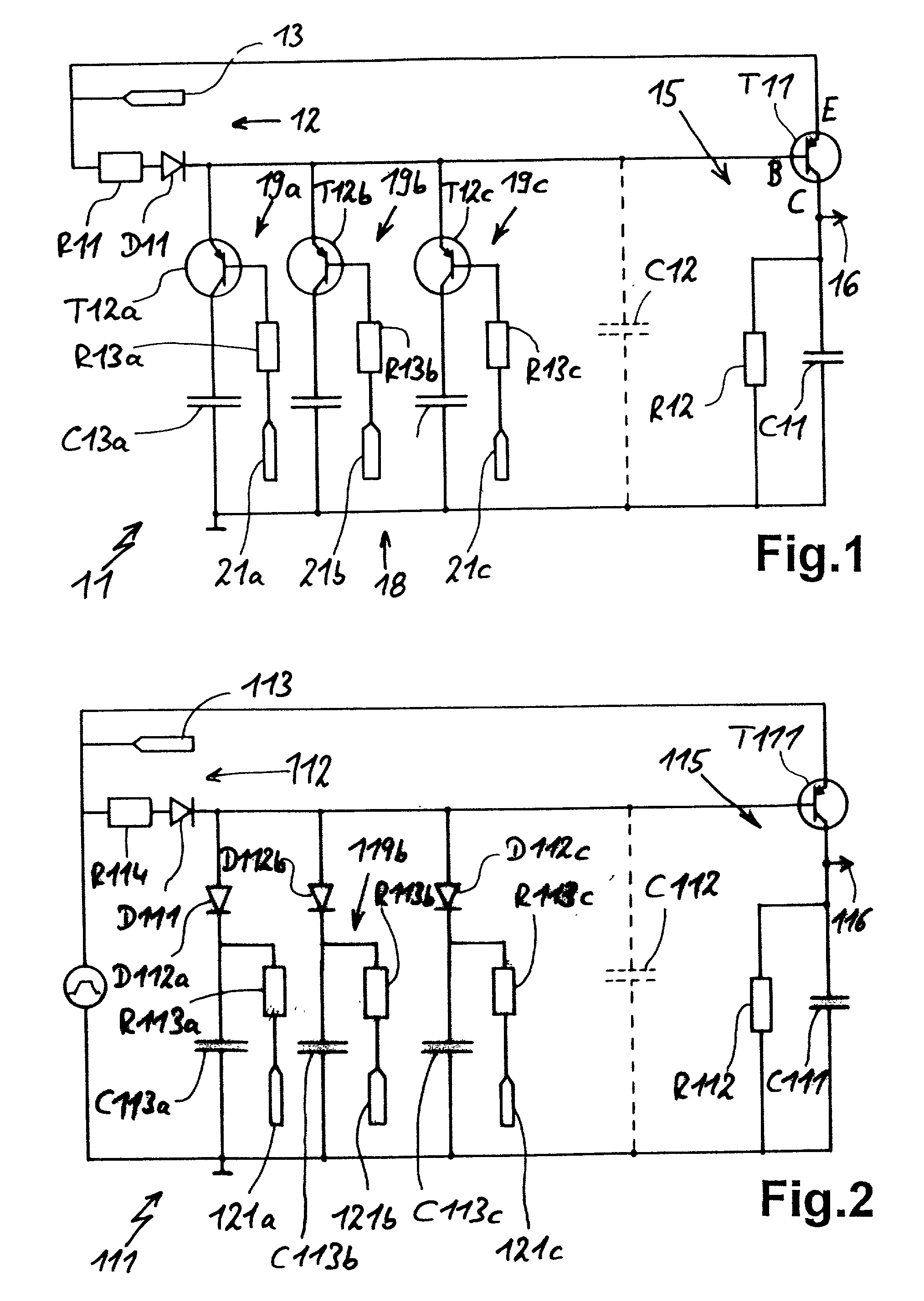
[0020] FIG. 1 shows a circuit layout, which is designed in exemplified manner for the evaluation of three capacitive touch switches. In a simple modification, it is obviously possible to operate further touch switches. A control part 12 of the circuit 11 has a signal source 13 with a control signal. The control signal is preferably an alternating voltage signal or a unipolar square-wave signal. There are also a resistor R11 and a diode D11 in the control part 12.

[0021] The evaluating part 15 has a transistor T11, whose emitter E is connected to the signal source 13 and whose base B is connected to the diode D11. The collector C of T11 is placed against the basic potential of the circuit or ground by means of a parallel connection of a capacitor C11 and a resistor R12. By means of an output 16 it is possible to tap the output signal, which is applied as an analog signal to the capacitor C11.

[0022] The capacitor C12 constitutes a disturbance variable in the circuit and can be inserted...


PUM


Abstract

A circuit layout for several sensor elements of touch switches is described. It is subdivided into a control part with a control signal and a sensor part with several sensor branches, which in each case contain a capacitive sensor element. An evaluating part inter alia has a capacitor, where an analog output signal can be tapped. By means of connecting means, e.g. in the form of transistors or diodes, with a corresponding control in each case precisely one sensor branch is connected to the remaining circuit and the corresponding sensor element is controlled and evaluated.

Description

FIELD OF APPLICATION AND PRIOR ART[0001] The invention relates to a circuit layout for several sensor elements of several touch switches, the sensor elements having an operating state that changes as a consequence of operation.[0002] Such circuit layouts are known from the prior art, e.g. from EP 859 648. In the latter the sensor elements are permanently connected to the control means or the control signal is permanently applied. They are also permanently connected to the evaluating means, evaluation of the individual sensor elements taking place by means of a multiplexer. Thus, certain costs are involved with the said circuit layout, which prevent a more widespread use of touch switches.PROBLEM AND SOLUTION[0003] The problem of the invention is to provide a circuit layout for several sensor elements, which is simplified from the circuitry standpoint or can be implemented with lower component costs and which ensures reliable operation.[0004] This problem is solved by a circuit layou...

Claims


Application Information

Patent Timeline
IPC IPC(8): H03K17/967H03K17/94H03K17/96
CPCH03K17/94H03K17/96
Inventor GREMM, OLIVER
Owner E G O ELEKTRO GERAETEBAU GMBH
Why Eureka
Try Eureka