Planing sailboard

a technology for sailing boards and sailboards, which is applied in the field of watercraft sailing boards/windsurfers, can solve the problems of not being as fast as planing "slalom" or short boards, not plane well, and boards like the commercially available pro-tech c. a. t. are wide and short, and very fas

Inactive Publication Date: 2003-01-02
KELLER JOHN H
View PDF5 Cites 10 Cited by
  • Summary
  • Abstract
  • Description
  • Claims
  • Application Information

AI Technical Summary

Benefits of technology

[0023] It is another object of the invention to provide a hull design which has a stable and consistent angle of attack when planing over a wide range of wind speed.
[0024] It is a further object of the invention to provide a sailboard hull having a stepped lower surface that reduces difficulty of the transition from displacement to planing operation and avoids other observed undesirable effects such as increased drag during displacement operation.
[0025] It is yet another object of the invention to provide a sailboard hull design which reduces the effect of small aspect ratios of a planing hull, particularly at planing speeds and provides an increased effective aspect ratio with correspondingly increased lift and reduced trailing vortices and correspondingly reduced induced drag.

Problems solved by technology

It follows that planing hulls must often represent a compromise between efficiency in the displacement and planing modes of operation, particularly where available motive power is limited such as when sails are employed.
For example, commercially available sailboards such as the Mistral Ultralight and the F2 race board are made for non-planing or marginal planing conditions and are long, narrow and streamlined but, as would be expected, do not plane well and are not as fast as planing "slalom" or short boards.
For example, some boards like the commercially available Pro-Tech C. A. T. are wide and short and very fast when planing but comparatively slower at displacement operation speeds in light winds.
Such short boards are also somewhat more difficult to control and "unfriendly" to inexperienced wind surfers.
If it is large so that it planes in low wind, it is not as fast in higher winds because it will assume too small an angle of attack.
However, increased "rocker" makes it plane more slowly and requires additional wind for planing due to the decreased angle of attack at the rear which may even cause friction where the bottom surface tries to leave the water.
Commercially available boards which are designed primarily to perform in light wind are generally too flat to perform well in higher wind.
Such boards are more flat and plane at an angle of attack less than the optimum 4.degree.-7.degree.; thus having increased wetted surface and associated drag.
However, it is not practical to use such expedients on a sailboard since control by the operator is impractical.
Further, for both boats and sailboards, such trim plates or hull shaping to the same purpose (which is effectively contrary to the function of rocker), if not properly set for the current speed, can cause an effect known as porpoising.
Porpoising is an unstable state in which excess lift at the rear or stern forces the bow lower in the water where rocker causes increased lift at the bow; resulting in an oscillatory pitching action and increased drag.
However, the discontinuity in the shape of the bottom surface also tents to increase drag (for reasons that have not previously been well-understood but intuitively thought to be related to a combination of turbulence and suction behind the step and deeper extension into the water) during displacement mode operation and increase the difficulty of the transition between displacement and planing conditions as well as increasing the power / speed required to reach planing conditions.
Reduced aspect ratio also increases induced drag and reduces the lift to drag ratio.
However, these reported effects have been confined to environments providing flow on both surfaces and not with planing surfaces.
These limitations are particularly critical where available power is limited as is the case with sailboards which operate solely under sail power and where the sail area is severely limited by the necessity of being held in place by a human operator, principally by balancing wind force with limited body weight.
Nevertheless, known designs of sailboard hulls only support such levels of performance within a limited range of conditions (e.g. wind speed, water surface chop, and the like), while the cost and size of sailboards and other practical considerations effectively prevent alternative use of sailboards of different designs to exploit particular conditions which may prevail at any given time.

Method used


Image

  • Planing sailboard
  • Planing sailboard
  • Planing sailboard

Examples


Embodiment Construction

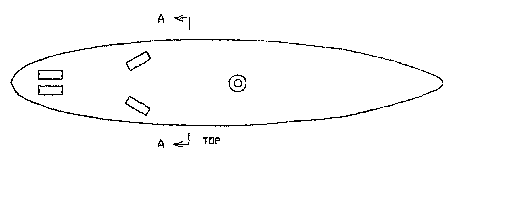
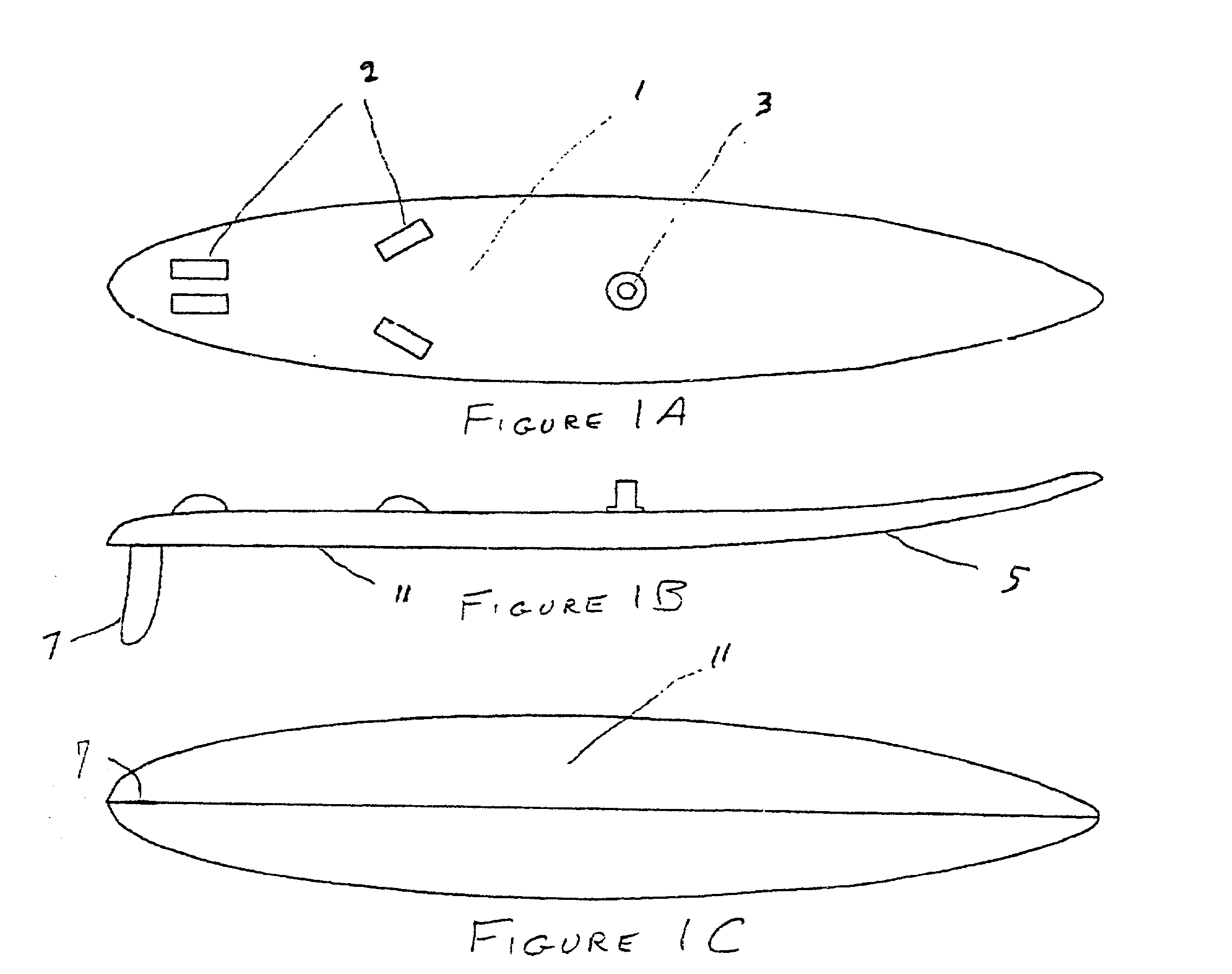
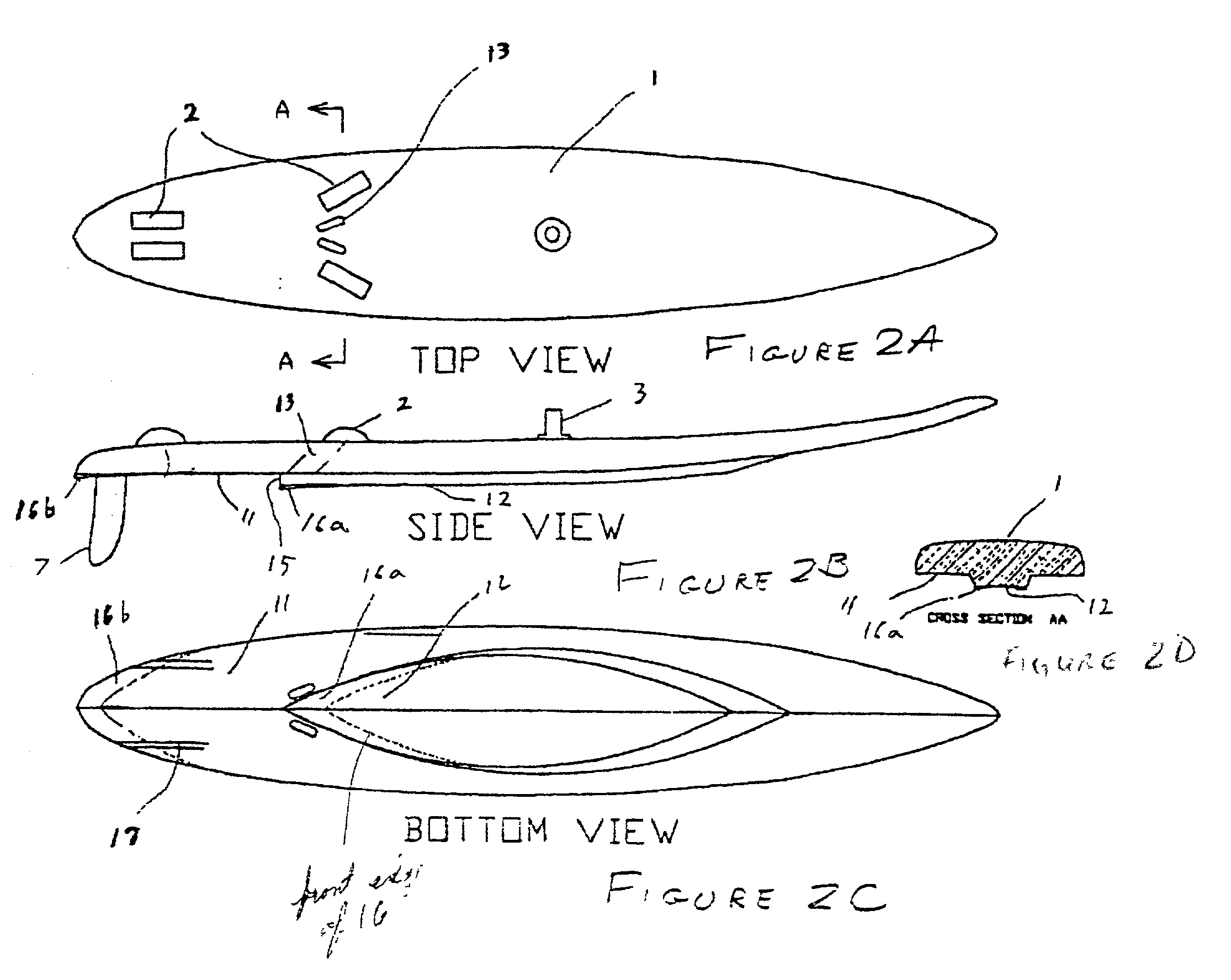
[0046] Referring now to the drawings, and more particularly to FIGS. 1A-1C, there is shown top, side and bottom views, respectively, of a generalized sailboard hull 1 which, for reference, does not include features in accordance with the invention in its various forms and embodiments. Since FIGS. 1A-1C are generalized and arranged for illustrative purposes, however, no portion of these Figures is admitted to be prior art as to the present invention. The overall shape in the top or plan view of FIG. 1A is generally elliptical but may be slightly more pointed at the front or rear. foot straps 2 and a sail or mast foot (generally gimballed) are installed on the upper surface of as shown in FIGS. 1A and 1B. A gentle upward curve or "rocker" is illustrated in the side view of FIG. 1 at reference numeral 5. A fin 7 is shown extending from the bottom surface 11 of the board in the side and bottom views of FIGS. 1B and 1C. The bottom side of the board, as shown in FIG. 1C, is also shaped in...


PUM


Abstract

High performance of a sailboard is achieved over a wider range of wind and water conditions by providing a hull having two or more planing surfaces which may differ in shape and / or aspect ratio. Drag due to suction at steps between planing surfaces is reduced by venting to the air. Cusp shaping of the respective planing surfaces can reduce and stabilize the angle of attack at the displacement / planing transition without causing fore-and-aft pitching effects known as porpoising. By confining water under the planing surfaces to reduce lateral outflow thereof through increased downward curvature of the bottom of the board, winglets, asymmetrical fins, fences and the like, the effective width and aspect ratio of the wetted area may be altered beyond that of the actual geometry of the planing surfaces to further increase lift and reduce drag while providing additional sources of lift at displacement, transitional and planing speeds. Steps and / or cambered shapes of the planing surface may be used to dramatically further reduce wetted area and further increase effective aspect ratio.

Description

[0001] This is a continuation-in-part of U.S. patent application Ser. No. 09 / 867,437, filed May 31, 2001, hereby fully incorporated by reference, of which application, priority is hereby claimed as to all common subject matter.[0002] 1. Field of the Invention[0003] The present invention generally relates to planing hulls for watercraft and, more particularly, to planing hulls for sailboards / windsurfers for improving the transition from displacement operation to planing operation and exhibiting increased speed over a wider range of wind speed.[0004] 2. Description of the Prior Art[0005] Hulls of watercraft may be of either of two distinct types: a displacement hull which derives vertical lift from the weight of water displaced by the hull and a planing hull which derives vertical lift from thrusting water downwardly by the bottom surface of the hull when in motion. At rest or at low speed, planning hulls function in the same manner as displacement hulls. Displacement hulls are most e...

Claims


Application Information

Patent Timeline
Patent Type & Authority Applications(United States)
IPC IPC(8): B63B1/20B63B35/79
CPCB63B1/20B63B35/7906B63B35/792B63B35/7926B63B35/7953B63B2001/201B63B2001/202B63B2001/206B63B32/50B63B32/55B63B32/60
Inventor KELLER, JOHN H.
Owner KELLER JOHN H
Why Eureka
Try Eureka