
Array for the transmission of electrical signals between moving units at a reduced number of paths

Inactive Publication Date: 2003-01-23
SCHLEIFRING & APPBAU
View PDF0 Cites 25 Cited by
  • Summary
  • Abstract
  • Description
  • Claims
  • Application Information

AI Technical Summary

Benefits of technology

[0015] According to a further expedient embodiment of the invention, a symmetry transformer is provided in the path of the filter between the signal transmission paths and the signal source or sink, respectively, in the case of a symmetrical signal transmission. This symmetry transformer ensures a wide-band high suppression of non-symmetrical signals such as those occurring in the case of a high leak current through the protective conductor on the sliding paths. Voltage drops caused by contact noise are equally suppressed over a wide range because they occur only as non-symmetrical signals, too.

Problems solved by technology

In a sliding contact system of the conventional structure, a low-impedance transition through the sliding contact is never ensured with 100% reliability.
Hence one cannot preclude, not even in the case of a fault, that the protective conductor function is inappropriate or does not at all exist as a result of contact trouble that may be caused by corrosion, contact bounce or a mechanical defect.
When DC or low-frequency signals of a higher intensity are transmitted via sliding paths the contact noise of the sliding contacts gives rise to a high-frequency voltage drop on these paths, which cannot be neglected.
Hence, not even the voltage drops occurring as a result of contact noise lead to substantial signal interference or noise in the control signals.

Method used


Image

  • Array for the transmission of electrical signals between moving units at a reduced number of paths
  • Array for the transmission of electrical signals between moving units at a reduced number of paths
  • Array for the transmission of electrical signals between moving units at a reduced number of paths

Examples


Embodiment Construction

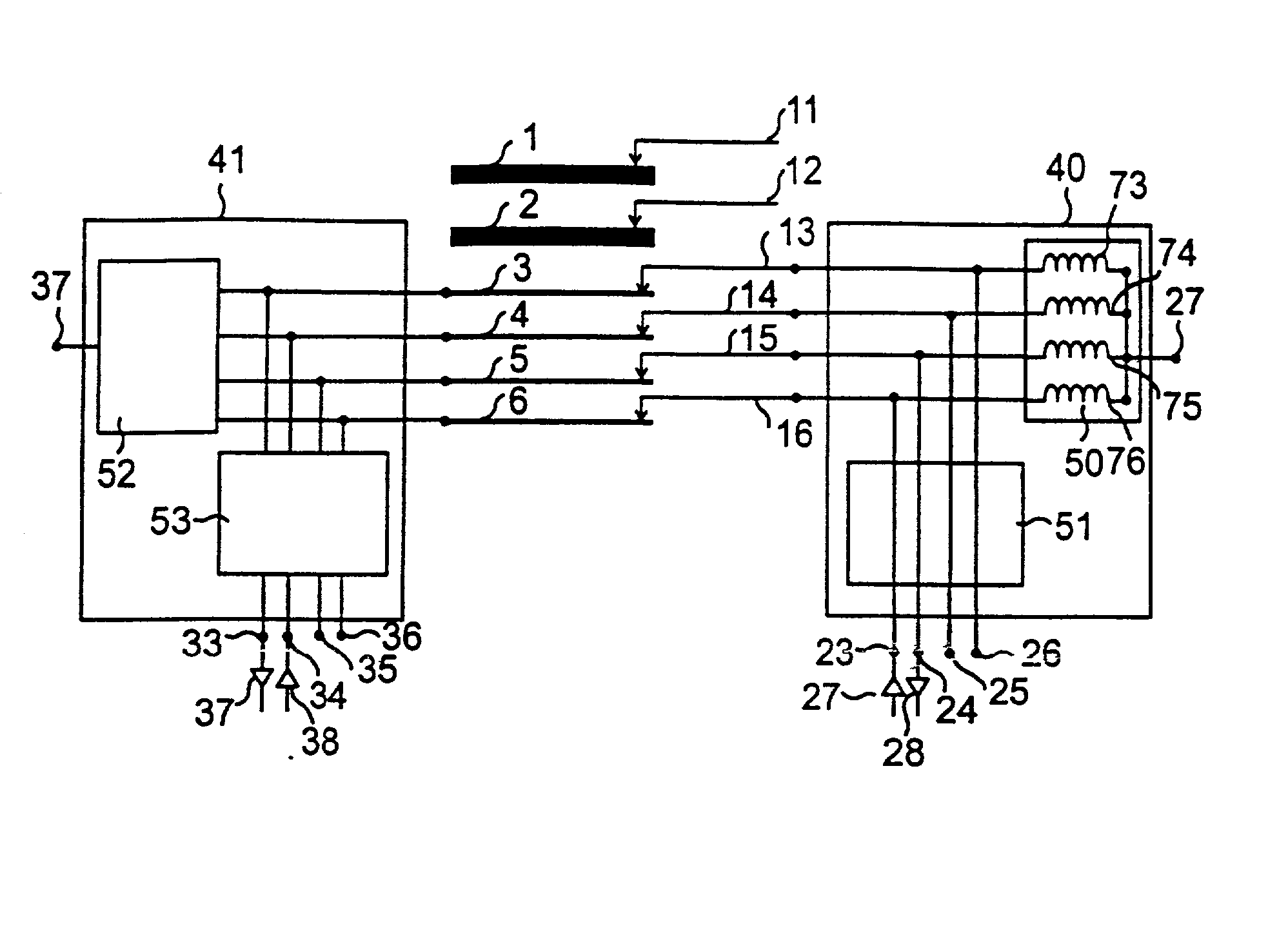
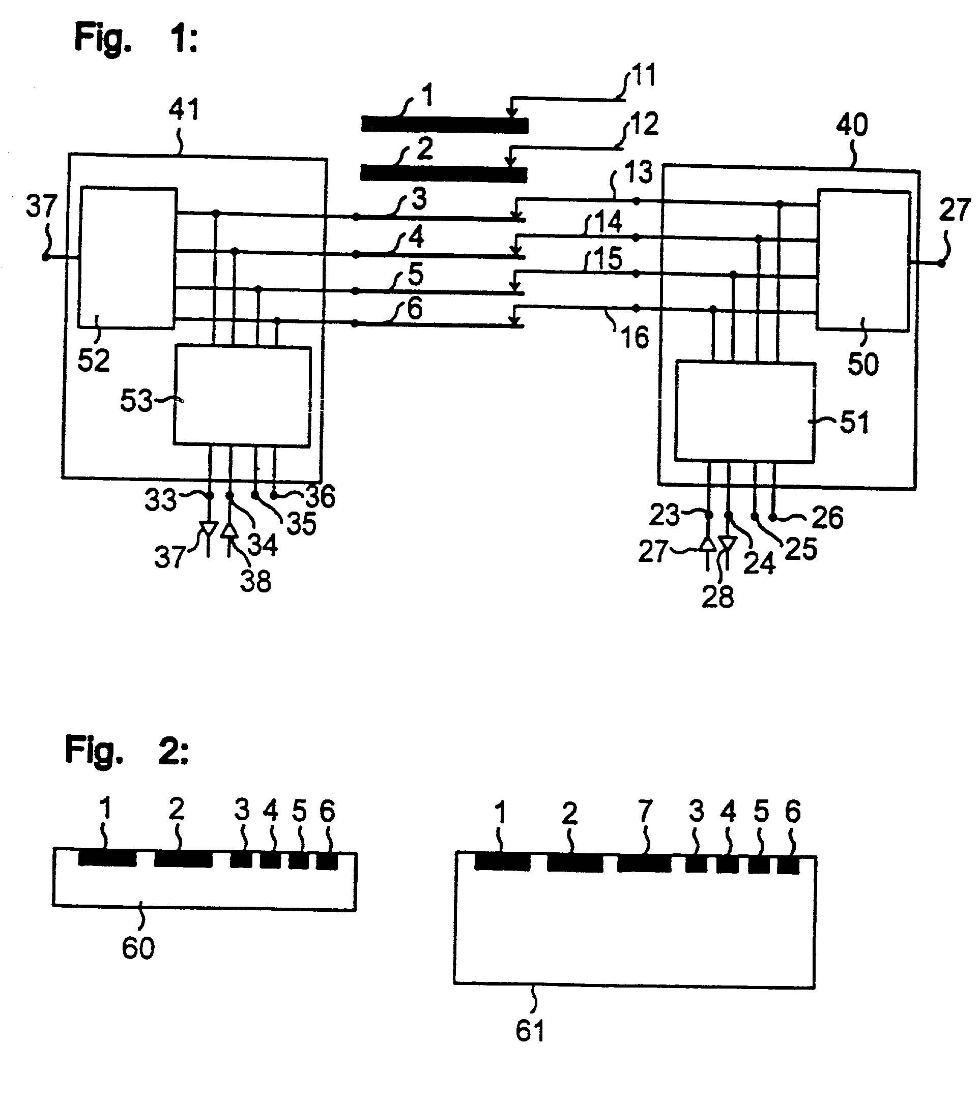
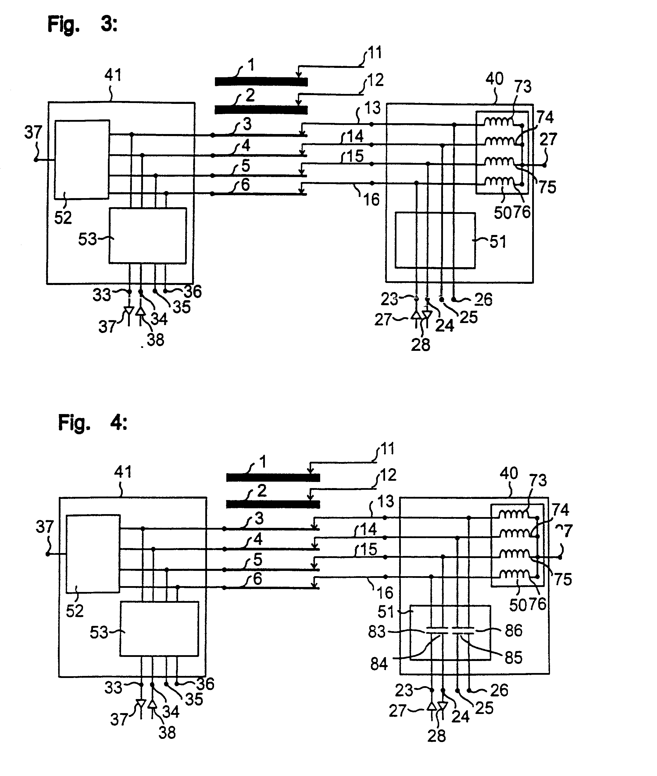
[0022] FIG. 1 illustrates an inventive array by the example of a linear sliding path system. The principle of the invention can, of course, also be applied to a rotationally symmetrical slip ring or even a transmission path with an optional trajectory. The sliding path system consists of the sliding paths (1 . . . 6) with the corresponding sliding contacts (1 . . . 16). In the system described here by way of example, the sliding paths (1, 2) as well as the associated sliding contacts (11, 12) are provided with a particularly high voltage-proof characteristic and a particularly high current load capacity for power transmission. All other sliding paths and sliding contacts are exclusively designed for signal transmission for control signals. The sliding paths for the control signals well as the sliding contacts are connected via the filter units (40) or (41). The first filter (40) comprises a filter block (50) connecting the protective conductor terminal (27) with the signal transmiss...


PUM


Abstract

What is described here is an array for the transmission of electric signals and / or energy between units between units or parts mobile relative to each other, consisting of at least two electrical conductors matched with the trajectory of the movement on the first part and further parts in galvanic or at least capacitive or inductive contact, respectively, with these conductors. The inventive array is characterized by the provision that at least one of said electrical conductors, which serves at the same time for the transmission of control and / or data signals, is galvanically connected via a filter to said protective conductor such that it performs also the drain function of said protective conductor.

Description

[0001] This application is a continuation of pending International Application No. PCT / DE00 / 04263 filed Nov. 30, 2000, which designates the United States and claims priority of German Patent Application No. 199 57 621.1 filed Nov. 30, 1999.[0002] The present invention relates to an array for the transmission of electric signals and / or energy between moving units that may be disposed along an optional trajectory and are in galvanic or at least capacitive or inductive contact, respectively, with each other.PRIOR ART[0003] Electric signals or electric energy must frequently be transmitted between units or parts moving relative to each other. A common method used to this end is the use of sliding paths and slip rings. Here, the signal or the energy, which is supplied on a linear conductor or even a conductor disposed on a circular trajectory, is derived by means of a mobile tap. Such taps may consist of contact springs or even graphite elements permitting an appropriate galvanic contact...

Claims


Application Information

Patent Timeline
IPC IPC(8): A61B6/00H04B5/00
CPCA61B6/56H04B5/00H04B5/0012H04B5/0018H04B5/0093H04B5/28H04B5/22H04B5/266
Inventor LOHR, GEORG
Owner SCHLEIFRING & APPBAU
Learn More