
Low loss interconnection for microwave switch array

a low-loss, interconnection technology, applied in waveguide devices, electrical equipment, instruments, etc., can solve the problems of laborious connection of two or more upper and lower switch cards, and increasing the insertion loss of these lines to an objectionable value, etc., to achieve the effect of reducing the cube size, improving the insertion and reflection loss, and reducing the cos

Inactive Publication Date: 2003-01-23
TERABURST NETWORKS
View PDF0 Cites 6 Cited by
  • Summary
  • Abstract
  • Description
  • Claims
  • Application Information

AI Technical Summary

Benefits of technology

0062] One advantage of this type of switch assembly is to minimize cost by avoiding the use of expensive individual mechanical RF connectors in each assembly. Other advantages include: the pitch between the RF feedthroughs being reduced by 2.times.; the size of the cube being reduced by 2.times.; and the RF losses being reduced by a factor =>2.times. (because of smaller RF paths on the smaller cards, enabled by the present invention). Also, the removal of Gilbert connectors improves insertion and reflection losses. Still another advantage is that the reduced cube size now allows the usage of alumina switch cards which have much less microwave absorption loss compared to other materials. Finally, the disclosed embodiment allows for ease of addition and replacement of switch cards using local Joule heating of solder bumps.
0064] Thus, what has been described is a low-loss, inexpensive, compact, easy-to-assemble, easy-to-maintain microwave switch array with reduced losses and reflections, and methods of making and assembling such a switch array.

Problems solved by technology

The digital control can be complex if there are many switches in series.
However, the length of the transmission lines near the edge of a 12 inch board may cause an increase in the insertion loss of these lines to an objectionable value, on the order of 10 dB per decade in frequency.
Furthermore, connecting together two or more upper and lower switch cards may be labor intensive and require many electrical connectors.
Also, disassembling and / or reworking such switches may be difficult.

Method used


Image

  • Low loss interconnection for microwave switch array
  • Low loss interconnection for microwave switch array
  • Low loss interconnection for microwave switch array

Examples


Embodiment Construction

[0036] 1. Introduction

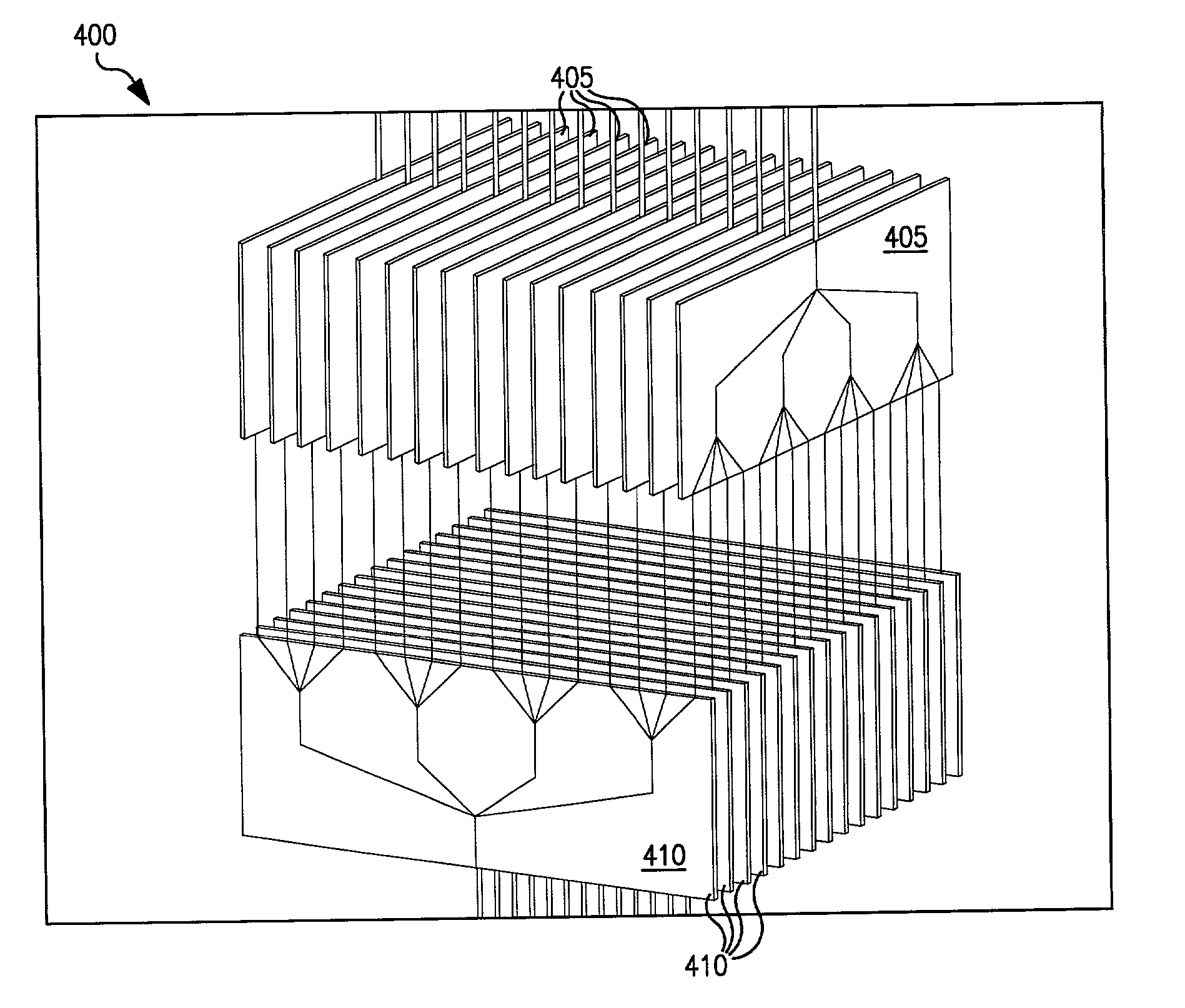
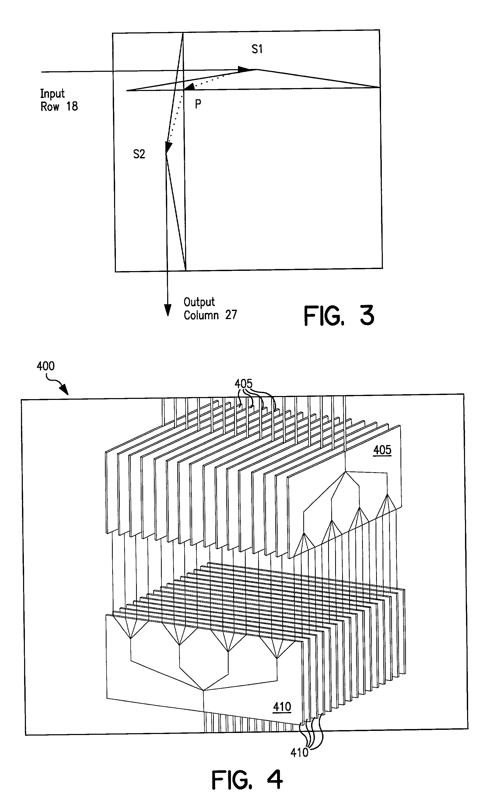
[0037] In general, the present invention provides structure and methods for enabling fast, efficient coupling between upper and lower switch cards, for example, those depicted in FIG. 4. However, the person of ordinary skill in the switching art will recognize that the advantages of the present invention may be applied to other areas of coupling design as well. Briefly, the preferred embodiment disposes "wells" at the mating edges of each of the upper and lower switch card, the wells being adapted to contact complementary conductor posts carried by a connector board that is placed between the upper and lower switch cards. The posts preferably have solder balls which protrude from the upper and lower surfaces of the connector board. This way, placement of the connector board between the arrays of upper and lower switch cards will enable immediate electrical coupling between all of the signal paths of the upper and lower switch cards. The connector board may also...


PUM


Abstract

Microwave switching method and apparatus useful in high frequency operations (~40 GHz) includes structure and / or steps for providing a plurality of parallel upper switch cards, each having at least one input and a plurality of outputs; and a plurality of parallel lower switch cards, each having a plurality of inputs and at least one output. The plurality of lower switch cards is disposed perpendicular to the plurality of upper switch cards. A connector board is disposed between the edges of the plurality of upper and lower switch cards, the connector board having a two-dimensional planar array of electrical-coupling terminals for electrically coupling the plurality of upper switch cards outputs to the plurality of lower switch card inputs. Preferably, the electrical-coupling terminals comprise solder bumps disposed at either end of metallized via holes through the board, the solder bumps couple to wells disposed at the edges of the upper and lower switch cards.

Description

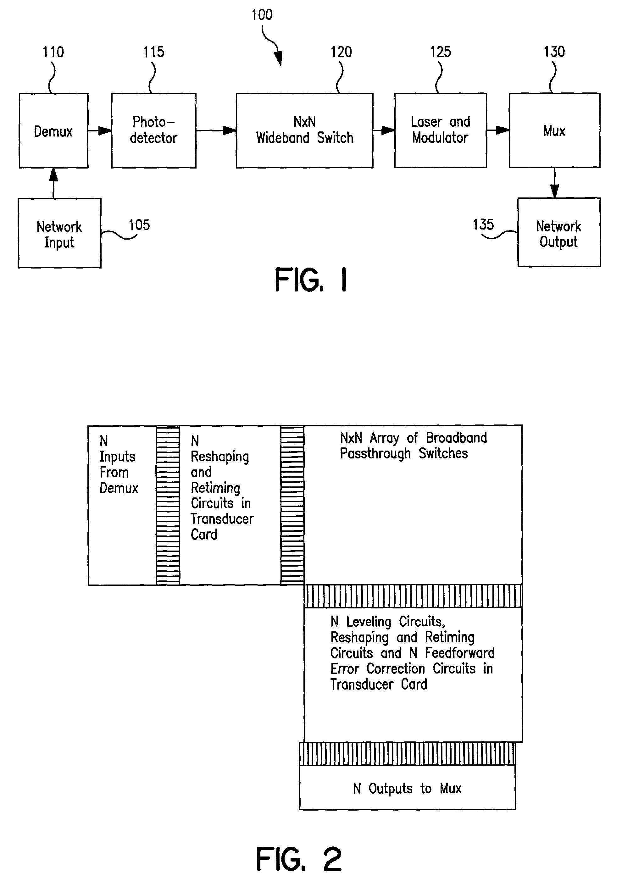
[0001] 1. Field of the Invention[0002] The present invention relates to an apparatus and a method for implementing a switching array for telecommunications, and more particularly to structure and process for coupling together upper and lower switch cards in a microwave switching array.[0003] 2. Description of the Related Art[0004] A basic optical-to-microwave-to-optical telecommunications system 100 is shown in FIG. 1. The system 100, which is described in U.S. patent application Ser. No. 09 / 727,171, filed on Nov. 29, 2000 and entitled "Crossconnect Switch With A Flat Frequency Response And A High Cutoff Frequency" and is incorporated herein by reference, comprises a network input 105, a demultiplexer 110, a photodetector 115, an N.times.N wideband switch 120, a laser and modulator 125, a multiplexer 130, and a network output 135. See also T0014 U.S. patent application Ser. No. ______, filed on Jul. 16, 2001 and entitled "Optical-Microwave-Optical Switching Array for Telecommunicati...

Claims


Application Information

Patent Timeline
Patent Type & Authority Applications(United States)
IPC IPC(8): H01P1/12
CPCH01P1/127
Inventor CHAN, ELIMLEVINE, JULES D.JAIN, MAHENDRAMCKLEROY, CHRIS
Owner TERABURST NETWORKS
Learn More