
Method for manufacturing automobile interior article

a manufacturing method and automobile technology, applied in the manufacture of butters, vehicular safety arrangments, buttons, etc., can solve the problems of increasing the number of assembly steps, difficult control of breaking positions and depths, and the cover may be broken when the airbag is activated, so as to improve productivity and poor reproduction

Inactive Publication Date: 2003-01-30
TOYODA GOSEI CO LTD
View PDF4 Cites 45 Cited by
  • Summary
  • Abstract
  • Description
  • Claims
  • Application Information

AI Technical Summary

Benefits of technology

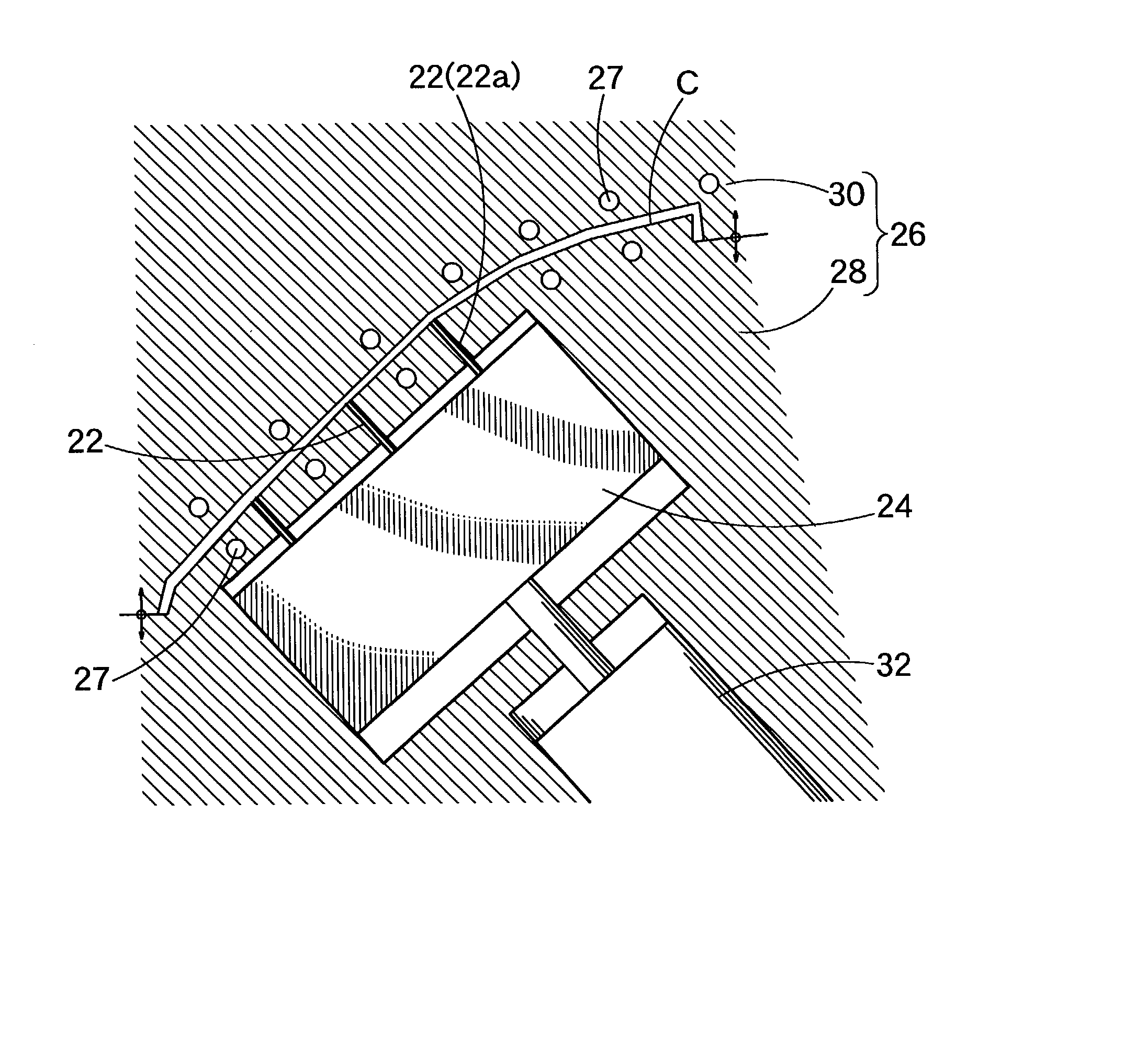
[0016] Alternatively, at the time of the forward movement of the tear line forming block, the temperature of the mold at its face forming the outer side of the molding, opposite to the tear line forming block, may be higher than that of the tear line forming block. The cooling and hardening from the outer side can thus be suppressed to reduce the resistance of the material to the stamping during tear line forming.
[0021] In the individual constructions thus far described, moreover, it is desired the tear line forming projections are made of a set of conical or frustoconical pins. The material flow is smoothed, and the leading ends of the individual pin holes to be formed by the tear line forming projection are tapered to facilitate the stress concentration and to stabilize the cover portion expandability.
[0022] Another object of the invention is to provide a surface portion thermal molding method for thermally molding (or vacuum molding) the surface portion of an automobile interior article having a portion for covering an airbag, suppressing rise in cost and reliably breaking off at tear line portions (portions to be broken). This object can be achieved by the following individual construction.
[0025] Because of the vacuum molding (or vacuum suction) by the female die, moreover, the die release (or die releasability) after the molding completion is better than the case of the vacuum molding by the male die, which improves the productivity.
[0028] In the construction described above, it is desired that the temperature (the tip temperature) of the blade (the groove forming blade or projection) the tear line forming blade is higher than the melting temperature of the rear side of the surface portion. The groove portions to be broken are curved (smoothed) on the bottom, all with an equal depth, and not affecting the design on the surface (design face). Specifically, the surface portion tear line portions (or grooves) are formed at the vacuum suction time so that the surface portion material easily escapes. When the grooves are to be thermoplastically deformed by the tear line forming blades (the groove shaping projections), there tends to be much variation in the degree of penetration so that there is much variation in groove depth thereby and also there is formation of ridges along the grooves on the design face side. If slits (or cut grooves) having an extremely small width are formed with the groove forming blade, moreover, there is similar variation in groove depth according to the sharpness of the blade. The variation in the groove depth may easily cause a difference in the breaking characteristics of the grooves to be broken.

Problems solved by technology

Therefore, a gap or abrupt shift in the surface is easily formed between the bag covering member and the panel body so that restrictions must be placed on the design, increasing the number of assembling steps.
Moreover, the cover portion of the panel or the hard resin body is required to have grooves or notches to be broken, so that the cover may be broken when the airbag is activated.
Moreover, it is difficult to control the breaking positions and depths, and costs rise as a result.
In case this technique is applied to a hard panel (or an automobile interior article body) made of a hard resin material, however, it has been found that extrusion marks due to the pushing of the groove forming projection (or the groove forming block) appear on the surface of the molding (design face), a problem which does not occur in the case of soft resin material.

Method used


Image

  • Method for manufacturing automobile interior article
  • Method for manufacturing automobile interior article
  • Method for manufacturing automobile interior article

Examples


Embodiment Construction

[0048] Here will be described embodiments of a manufacture method of an automobile interior article of the invention.

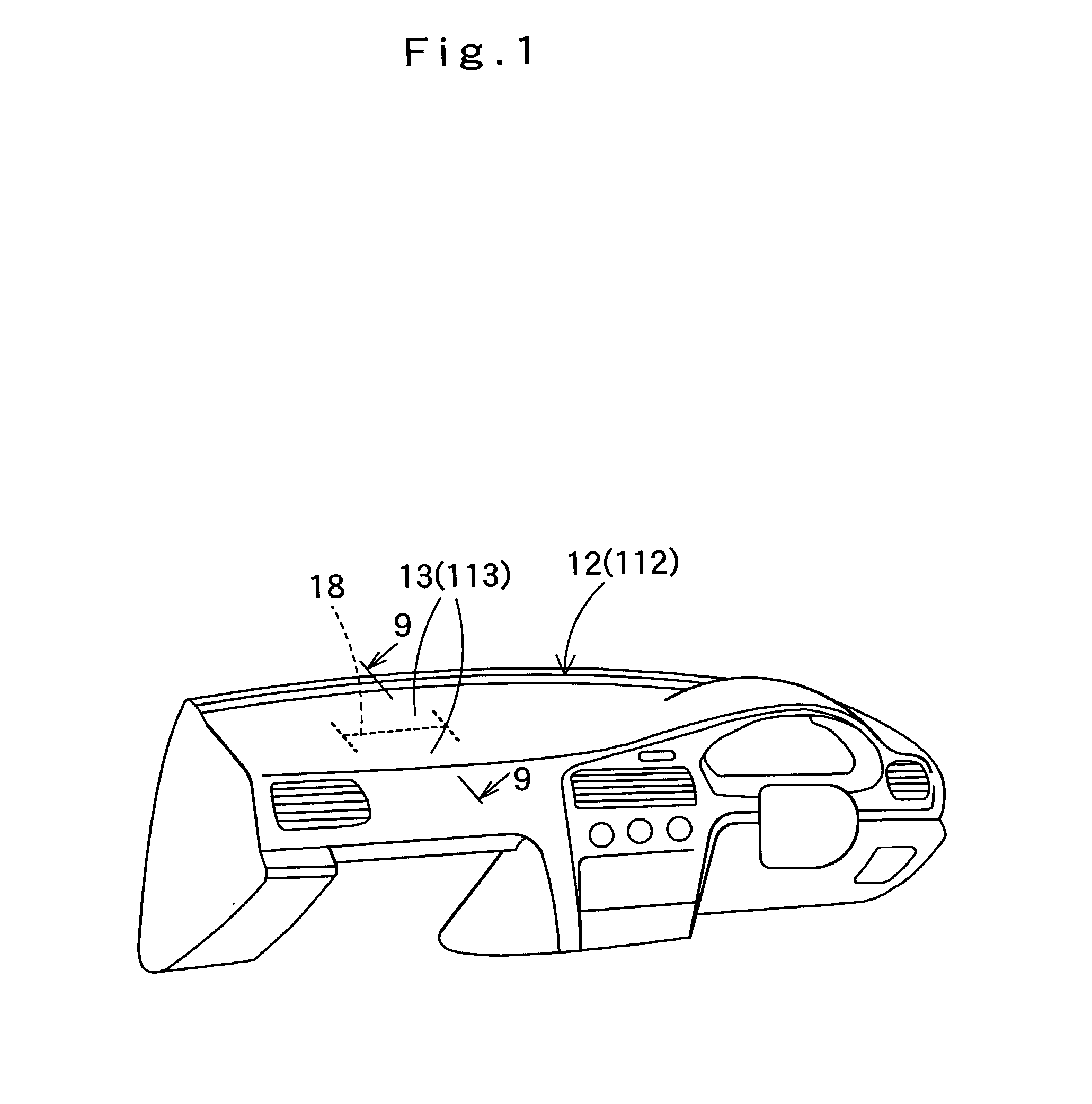
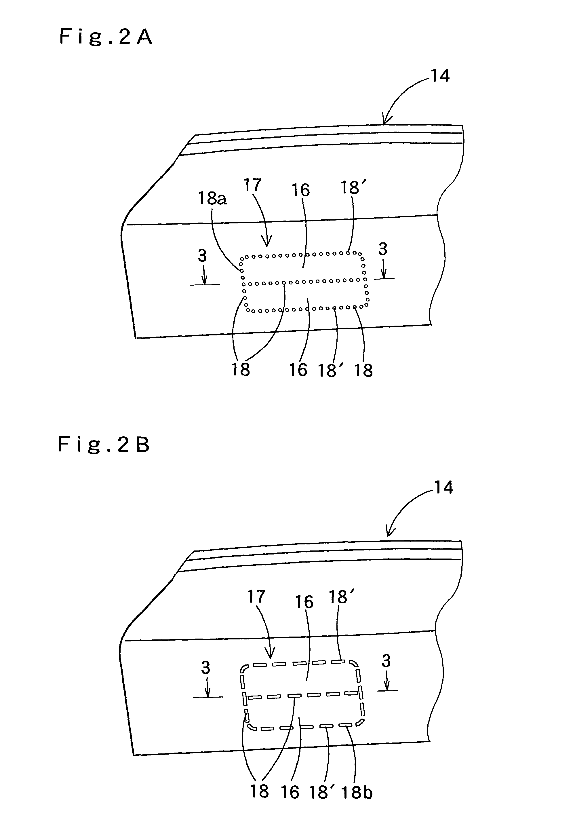
[0049] The automobile interior article equipped with a cover portion being developed from which an airbag inflates will be described on the case in which it is applied to a panel 12, as shown in FIGS. 1 and 2. FIG. 1 is a perspective view showing the panel 12 as a whole, and FIGS. 2A and 2B are back views showing an essential portion of a panel body 14.

[0050] This panel body (i.e., the automobile interior article body: or the hard resin body) 14 of the panel 12 is manufactured of a hard resin by an integral injection molding method to have a pair of front / rear cover portions 16 and 16, which can be opened like double leaves as in the prior art.

[0051] As the molding material and the hard resin, here can be enumerated PPC (carbon-filled polypropylene), PPT (talc-filled polypropylene), PC (polycarbonate) / ABS (terpolymer of acrylonitrile, butadiene and styrene), PC (polyc...


PUM

PropertyMeasurementUnit
Temperatureaaaaaaaaaa
Fractionaaaaaaaaaa
Timeaaaaaaaaaa

Abstract

A method for forming tear lines in the rear side of an automobile interior article having a cover portion being developed from which an airbag inflates. When either an automobile interior article body having an integrally molded surface portion or an automobile interior article surface portion is to be molded, the mold is opened after tear line forming projections are moved forward and backward with the mold closed. Thus, the tear lines can be formed at the molding time without any visible extrusion marks of the tear line forming projections on the front surface side (the design face).

Description

2. CROSS-REFERENCE TO RELATED APPLICATION[0001] The present application claims priority to Japanese Patent Applications No. 2001-228480 filed Jul. 27, 2001, No. 2001-346096 filed Nov. 12, 2001, and, No. 2001-361399 filed Nov. 27, 2001, the entirety of each is hereby incorporated into the present application by this reference.3. BACKGROUND OF THE INVENTION[0002] The present invention relates to a method for manufacturing by molding an automobile interior article body (or a hard resin body) in which an automobile interior article having a cover portion being developed from which an airbag inflates is integrally molded of a hard resin material.[0003] The invention will be described hereinafter mainly in connection with an instrument panel (hereafter abbreviated to "panel") having a cover portion for an airbag. However, the invention can also be applied to cover portions for airbags for side doors, pillars and front / back seats.[0004] In the so-called "hard panel" (the usual injection-mo...

Claims


Application Information

Patent Timeline
IPC IPC(8): B29C45/56B29C51/08B29C51/14B29C51/32B29C51/42B60R21/2165
CPCB29C45/5675B29C51/082B29C51/14B29C51/32B29C51/428B29C2793/0054B29K2023/12B29K2055/02B29K2069/00B29K2105/12B29L2022/027B29L2031/3008B29L2031/3038B60R21/2165
Inventor UENO, SHIGEHIRONAGANO, AKIYOSHISHIGENO, KAZUMICHIFURUTA, KENICHIYAMADA, TATSUOSUGIYAMA, KENJI
Owner TOYODA GOSEI CO LTD
Learn More