Timing recovery in data communication circuits

a data communication circuit and timing recovery technology, applied in data switching networks, data system details, pulse techniques, etc., can solve the problems of reducing the performance of detectors, the inability of oscillators in this sampling scheme to implement digitally, and the closing of the eye of the equalizer outpu

Inactive Publication Date: 2003-02-06
LSI CORPORATION
View PDF15 Cites 26 Cited by
  • Summary
  • Abstract
  • Description
  • Claims
  • Application Information

AI Technical Summary

Problems solved by technology

Therefore, there is a strong possibility that the eye of the equalizer output will close when switching from NDD to DD timing recovery.
The oscillator in this sampling scheme cannot be implemented digitally and parts of it are implemented in the analog domain.
However, a drawback of asynchronous sampling is that it needs dynamic buffers for the implementation of the interpolators, which may be problematic.
If the performance of the

Method used


Image

  • Timing recovery in data communication circuits
  • Timing recovery in data communication circuits
  • Timing recovery in data communication circuits

Examples


Embodiment Construction

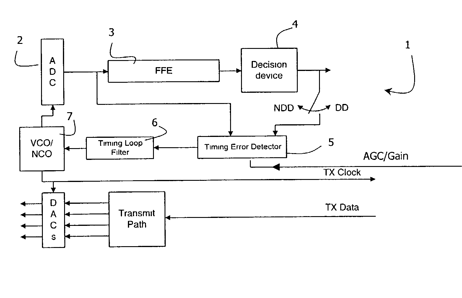
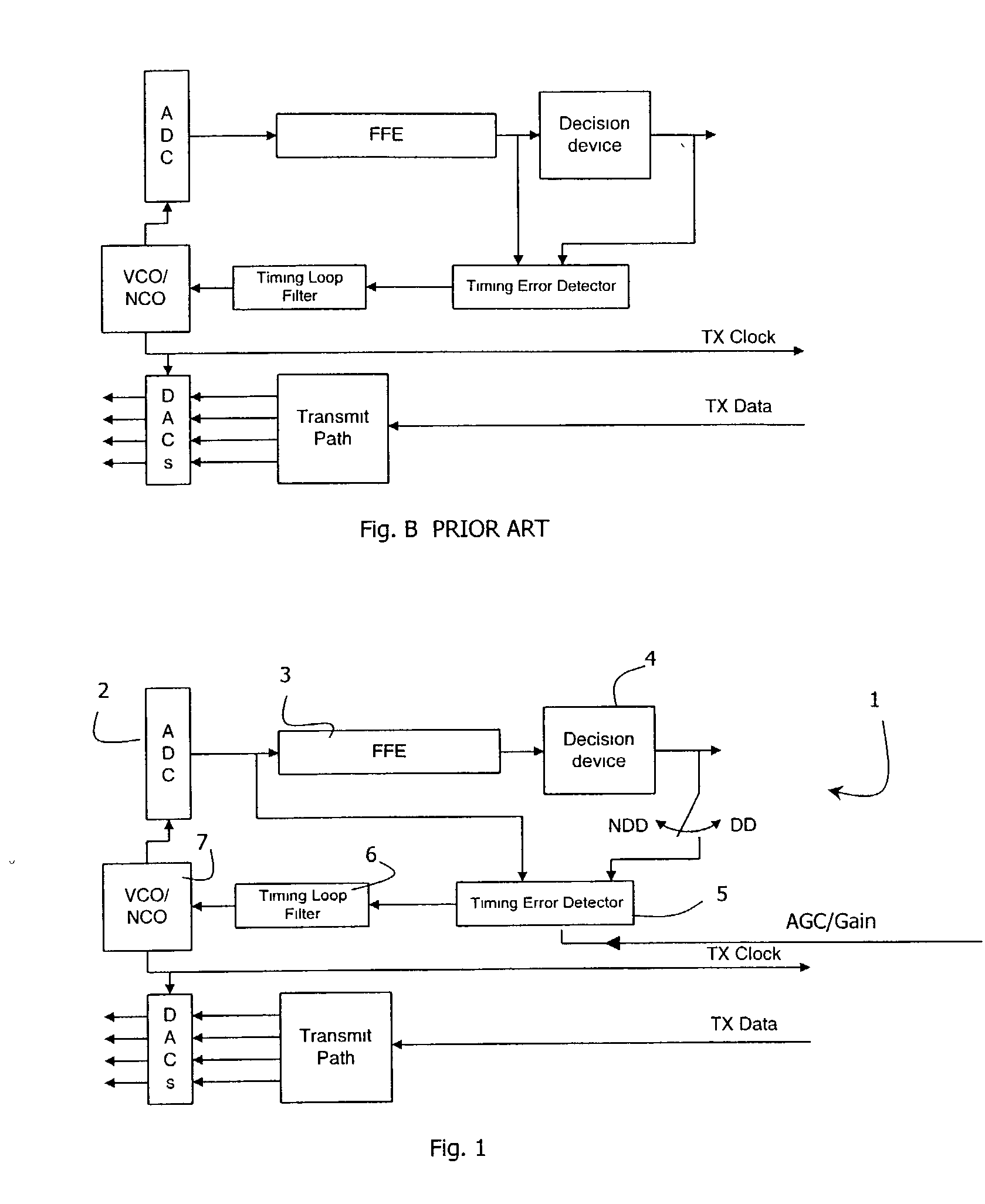
[0035] Referring to FIGS. 1 to 3 there is shown a timing recovery circuit 1 of the invention. The circuit comprises an ADC 2 connected to a FFE 3, in turn connected to a decision device 4. A timing error detector (TED) 5 has inputs from both the ADC 2 and the decision device 4 for DD recovery, and only from the ADC 2 for NDD recovery. Its output feeds a timing loop filter 6, in turn feeding a VCO 7. The TED 5 receives a gain value from the AGC. This is proportional to the length of the cable at startup of the circuit 1.

[0036] Thus, unstable operations arising from timing error detection being affected by equaliser coefficients are avoided, because timing and symbol detection processes are independent.

[0037] The NDD timing recovery circuitry is completely decoupled from the FFE because it takes its input solely from the output of the ADC 2. This input is fed through a nonlinearity (the TED) and the error generated is passed into a control loop which drives the Numerically Controlled ...


PUM


Abstract

In a 1000 BASE-T transceiver, a timing error detector (TED, 5) receives its inputs directly from the output of an ADC (2) and from a decision device (4). Timing recovery is acquired in three stages: a non-decision directed (NDD) stage during which only the output of an ADC (2) are used for acquisition; a stage for acquiring the remote scrambler and predicting symbols; and a decision-directed (DD) stage during which locally predicted symbols are also used for acquisition. Because the timing error detector (TED, 5) does not take inputs from the FFE (3) there is no information about cable length, and so an input of gain from an AGC is used to indicate cable length.

Description

[0001] The invention relates to timing recovery in data communication circuits such as those for 1000 BASE-T ("Gigabit") communication.PRIOR ART DISCUSSION[0002] The 1000 BASE-T system requires that each two-point link consist of one device configured as MASTER and another device configured as SLAVE. A startup procedure is specified in the IEEE standard and this dictates that the SLAVE must transmit its data at the exact same rate at which the MASTER is transmitting its data. Nominally the transmission rate of the MASTER will be 125 MHz, however in reality this rate will vary by some small amount, .epsilon. due to crystal oscillator variations arising from factors such as process and temperature variations. It is a function of the SLAVE to determine the value of .epsilon. from the incoming received signal and to ensure that it transmits to the MASTER at 125 MHz+.epsilon.. This determination of .epsilon. is called timing recovery and is normally done using an implementation of a timi...

Claims


Application Information

Patent Timeline
IPC IPC(8): H04L7/00H04L7/02H04L7/033H04L12/403H04L25/03
CPCH04L7/0004H04L7/0062H04L7/0335H04L12/403H04L2025/03477H04L7/0334
Inventor MURRAY, CARL DAMIENCURRAN, PHILIPMOLINA NAVARRO, ALBERTO
Owner LSI CORPORATION
Why Eureka
Try Eureka