Method for using a bone densitometry system,with dual-energy x-radiation

Inactive Publication Date: 2003-02-06
COMMISSARIAT A LENERGIE ATOMIQUE ET AUX ENERGIES ALTERNATIVES
View PDF10 Cites 20 Cited by
  • Summary
  • Abstract
  • Description
  • Claims
  • Application Information

AI Technical Summary

Problems solved by technology

Furthermore, the geometry of these acquisition systems limits the geometric deformations related to the size of the detector, which in particular would result from the conicity of the X-ray beam.
It is more difficult to implement these cone beam systems than it is to use the other two families of systems.
"Cone beam" type systems that are commercially

Method used


Image

  • Method for using a bone densitometry system,with dual-energy x-radiation
  • Method for using a bone densitometry system,with dual-energy x-radiation
  • Method for using a bone densitometry system,with dual-energy x-radiation

Examples


Embodiment Construction

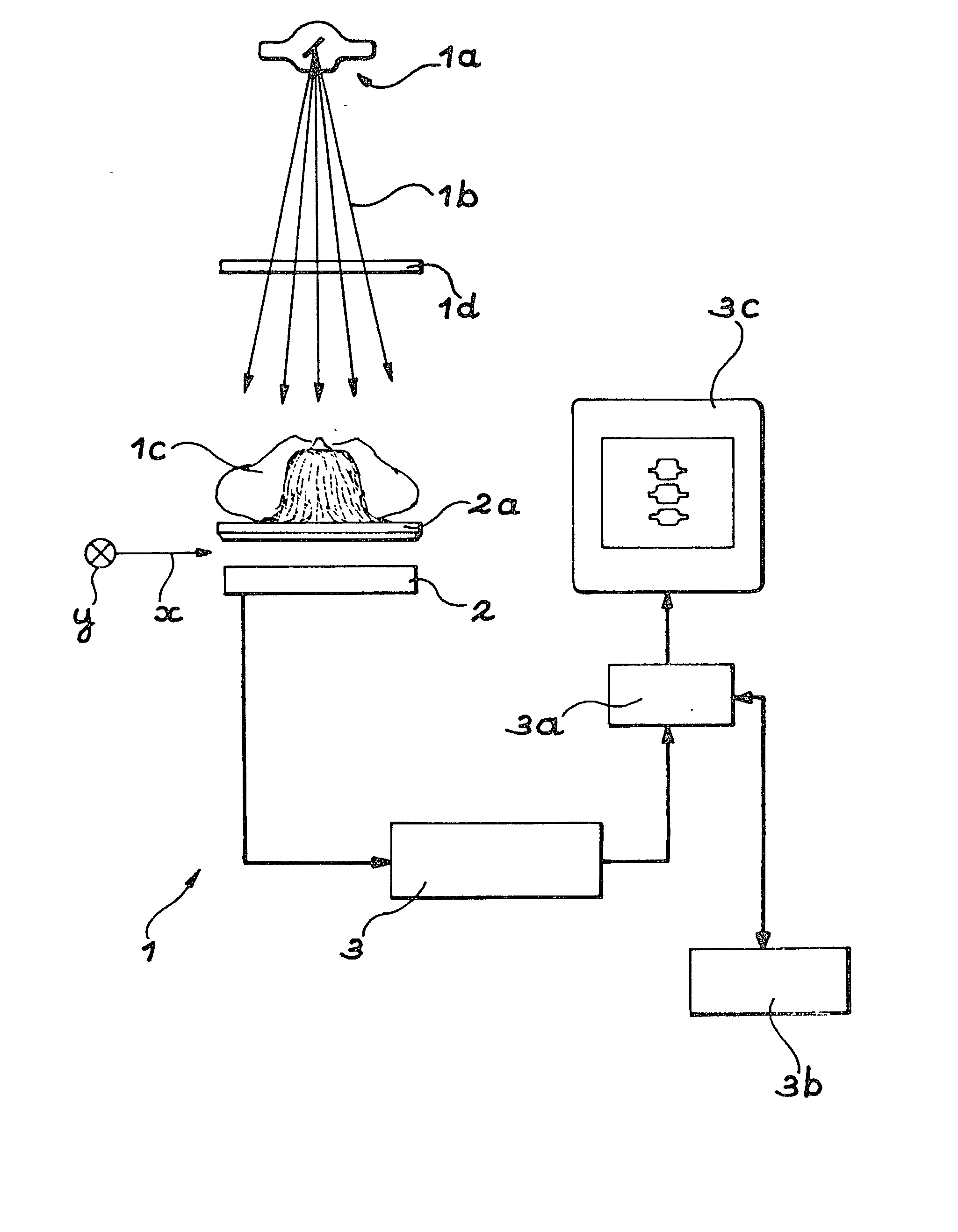
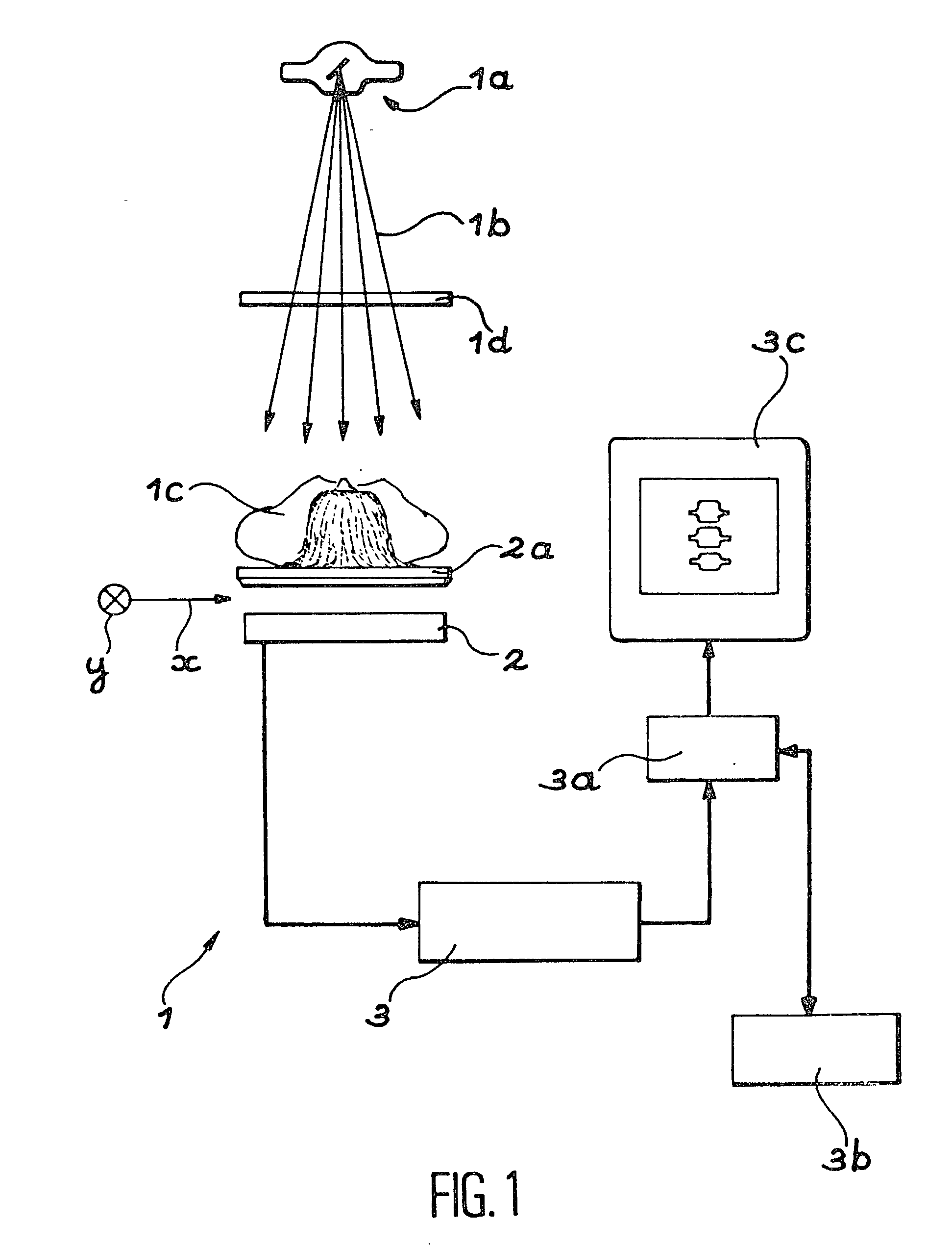
[0056] FIG. 1 shows a bone osteodensitometry system 1 that comprises an X-ray source la that can return a cone beam 1b of X-rays to the body of a patient 1c who is being examined. This source 1a can emit X-radiations corresponding to two different energy levels. These two levels are used to obtain two separate images of the patient.

[0057] A removable filter 1d can be inserted between the source 1a and the patient 1c and is used to improve the spectral qualities of the beam.

[0058] The system 1 also comprises a two-dimensional detector 2 that is very diagrammatically shown as a cross-section in FIG. 1 and is designed to detect X-rays emitted by the source after passing through the patient 1c. This detector 2 is parallel to a plane defined by two orthogonal directions x and y.

[0059] This patient is placed on an appropriate support 2a, for example a bed, that is transparent to X-rays. In the example shown in FIG. 1, the source 1a (provided with the filter 1d if required) is placed above...


PUM


Abstract

Process for use of an osteodensitometry system using dual-energy cone beam X-rays. The system (1) comprises an X-ray source (1a) capable of supplying a cone X-ray beam with at least a first energy called the high energy and a second energy called the low energy, a two dimensional X-ray detector (2) and electronic means (3a, 3b) for processing images supplied by this detector. According to this process, the low energy image of a part of the anatomy of a patient (1c) is acquired, and the high energy image of this part of the anatomy is acquired, and these images acquired at low energy and at high energy are matched before building up the map of bone densities of the part of the anatomy.

Description

[0001] This invention relates to a procedure for the use of an osteodensitometry system by X-rays.[0002] It will be remembered that osteodensitometry by X-rays is a technique for measuring bone masses and densities starting from radiographic acquisitions made at several energies.[0003] Two energies are usually used, called "high energy" and "low energy" respectively.[0004] Various configurations of a measurement system (X-ray source and detector) could be used to make the measurements.[0005] A distinction is made between three families of systems depending on the type of radiation used:[0006] pencil beam systems that use an X-ray source collimated through a hole and a X-ray monodetector that is also collimated,[0007] fan beam systems that use an X-ray source collimated through a slit and a linear X-ray detector, and[0008] cone beam systems that use a two-dimensional X-ray detector.[0009] More particularly, the invention relates to the implementation of osteodensitometry systems by d...

Claims


Application Information

Patent Timeline
IPC IPC(8): A61B6/00G06T1/00
CPCA61B6/405A61B6/583A61B6/505A61B6/482
Inventor DINTEN, JEAN-MARCROBERT-COUTANT, CHRISTINE
Owner COMMISSARIAT A LENERGIE ATOMIQUE ET AUX ENERGIES ALTERNATIVES
Why Eureka
Try Eureka