
Cutting mat for material sampling

a cutting mat and material technology, applied in the field of samples, can solve the problems of minute artefacts that can become lodged or embedded, and the nature of samples, and achieve the effects of easy transportation and use, high rockwell hardness, and strong practicability

Inactive Publication Date: 2003-02-27
GE HEALTHCARE BIO SCI CORP
View PDF0 Cites 10 Cited by
  • Summary
  • Abstract
  • Description
  • Claims
  • Application Information

AI Technical Summary

Benefits of technology

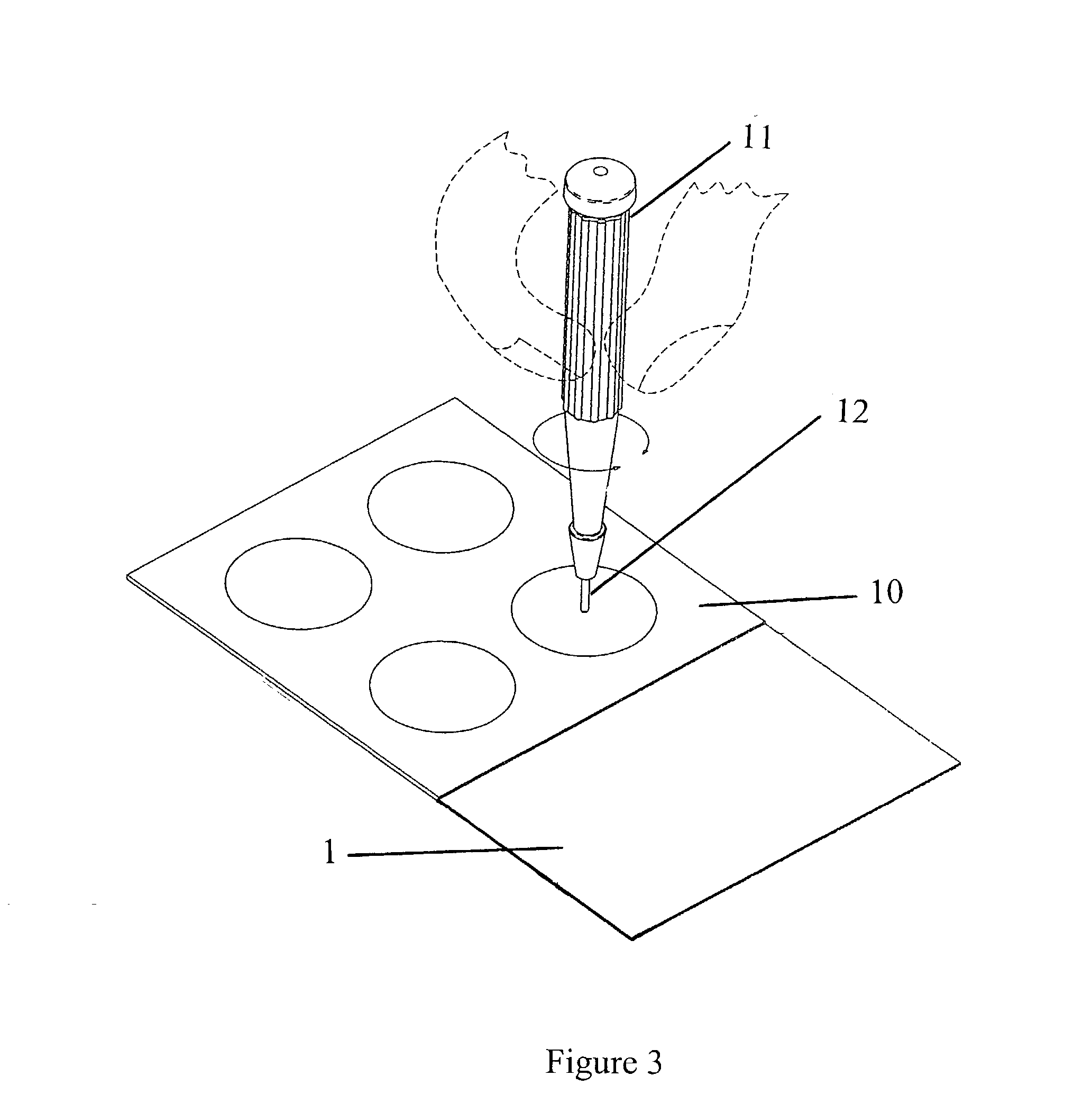
[0008] In a preferred embodiment of this invention, the deficiencies of the prior art devices are resolved by a manufactured extruded sheet of clear, anti-static, fully amorphous co-polymer (such as polyester resin glycol component (PET--Polyethylene terephthalate), poly styrene or other), a thermoplastic, cut to any desired size to support source materials which may be portioned with a sharp cutting device into smaller samples for the purpose of scientific analysis. Unlike the prior art, our invention generates a clear, visual record of the penetration of the cutting device in the mat surface. This is of value for repeat sampling of dried materials as there may be an interest to reuse the cutting mat to sample different dried materials or the same dried material (i.e. repeated sampling of dried blood on a blood filter cards or on clothing at a crime scene). This visual record enables the user to conduct subsequent sampling without penetrating a prior cut line on the mat. For viscous or semi liquid materials such as human or animal tissue, the inexpensive cost of each cutting mat increases the likelihood of preferred disposal after each use thereby avoiding potential cross contamination which is possible with these viscous materials. The nature of the materials sampled are susceptible to leaving minute artefacts which can become lodged or embedded in the cut line penetrating the surface of the cutting mat. This is also true in the prior art, however, in the example of the polyvinyl / rubber cutting mat, the restorative characteristic which is activated upon removal of the cutting device from the cut line, conceals previous cut lines produced during prior sampling of source materials and therefore also conceals the artefacts left behind during this prior sampling.
[0009] A further advantage of our invention in addition to the inexpensive unit cost is the ability to produce our mats in dimensions to not only suit any preferred material size but dimensions which can be designed for registration with pre-designed substrates such as sheets of paper, blood cards of different dimensions, etc. For instance our invention may be cut to the same dimensions as an FTA.TM. blood filter card. The plastic cutting mat may be positioned within the blood filter card, thus becoming associated with this particular blood filter card. All samples cut from this blood filter card would be prepared on the same cutting mat without concern for overlapping cut lines. This registration of the mat with the card allows the mat to become a permanent record of the size and number of samples collected from a particular corresponding blood filter card in the event the card is lost, destroyed or sampled without prior authorization. Similar pre-cut cutting mats may be prepared for registration with other standard size collecting substrates such as sheets of paper bearing ink, copier toner sheets, correction fluid on paper, credit card materials or currency notes which may require ink, paper or security fibre analysis when suspected of being counterfeit. Manufacturers of ink or paint maintain what is described as draw samples on large, paper board sheets which can be registered with similar sized mats thereby allowing one mat to be assigned to each sample substrate.

Problems solved by technology

The nature of the materials sampled are susceptible to leaving minute artefacts which can become lodged or embedded in the cut line penetrating the surface of the cutting mat.

Method used


Image

  • Cutting mat for material sampling
  • Cutting mat for material sampling
  • Cutting mat for material sampling

Examples


Embodiment Construction

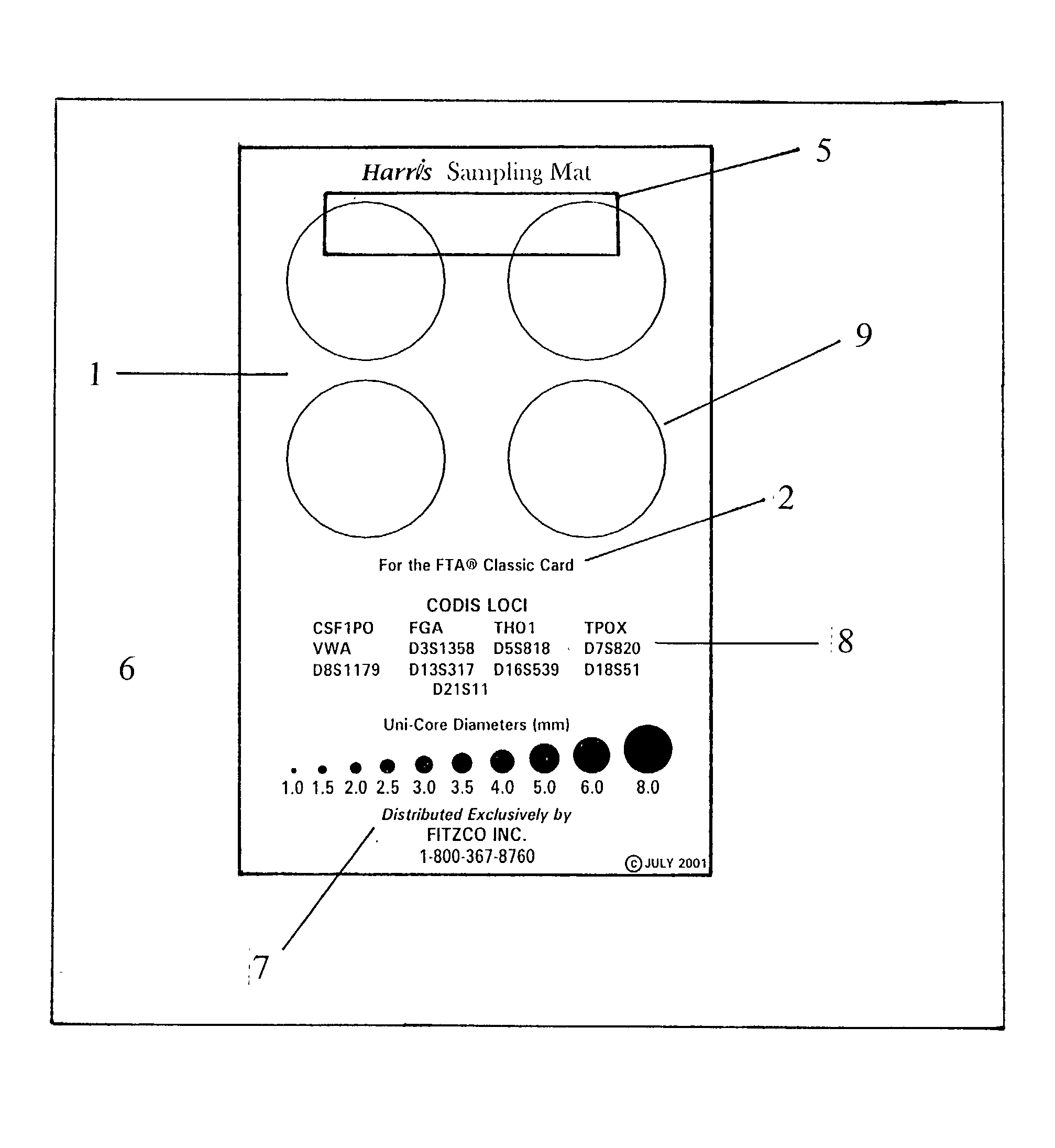
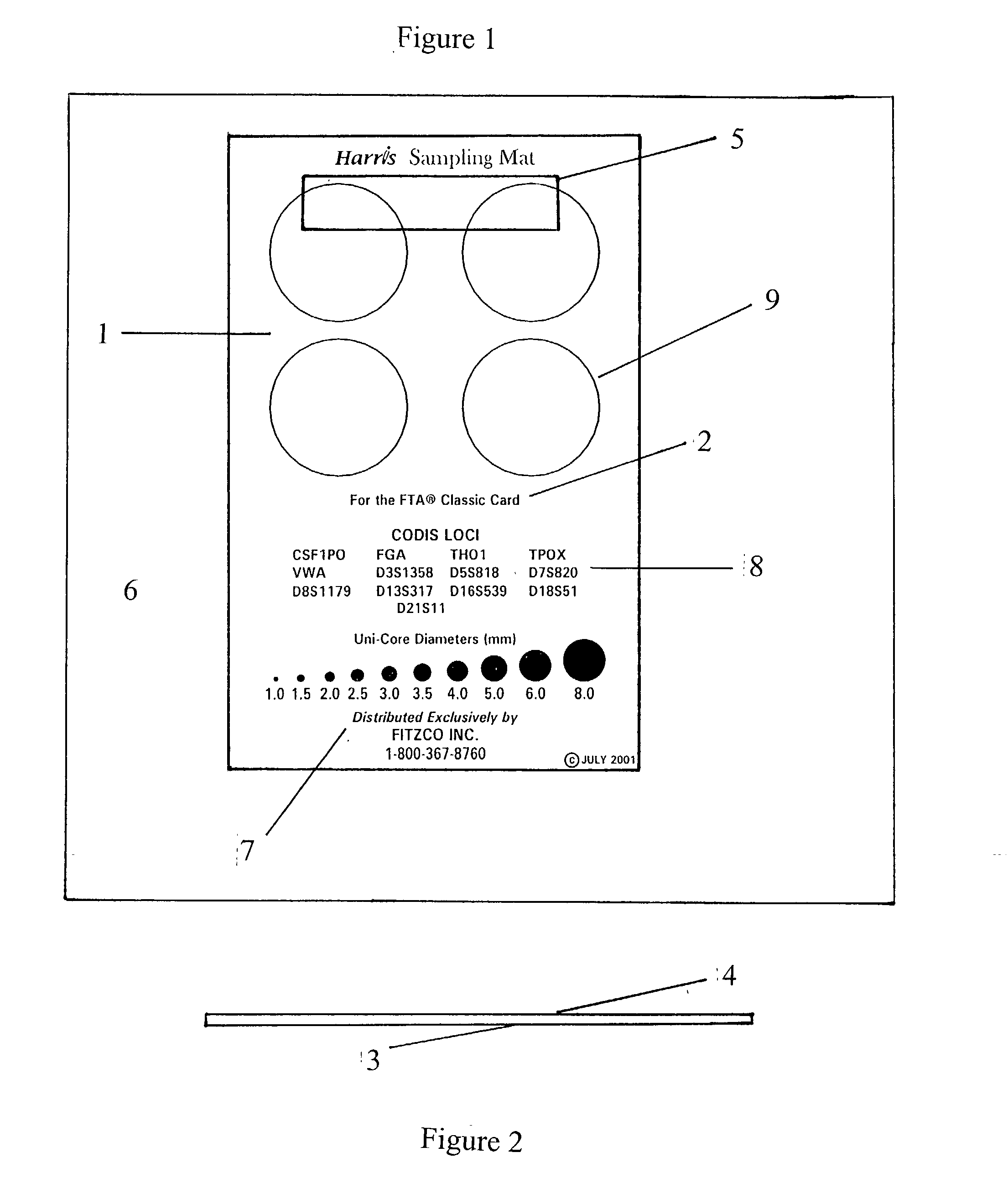
[0022] Referring to FIG. 1, a preferred embodiment of a recordable cutting mat for sample collection constructed in accordance with the principles of the invention is shown. A cutting mat 1 of preferred dimension bearing printed detail 2 on the bottom side cutting surface 3 which can be read from the top side cutting surface 4. An adhesive strip 5 positioned on the bottom side 3 of the mat 1 is used to adhere the mat 1 to a surface 6 to prevent slippage, possible injury during sampling and to free both hands to better manipulate the source material to be sampled and cutting device used. The mat 1 is cut from a larger manufactured extruded sheet of plastic. The mat 1 may be cut to any size from a larger source of mat.

[0023] In a preferred embodiment the sheet is fully transparent allowing for printed detail 2 on the bottom side 3 of the mat 1 to be viewed through the top side 4 of the mat 1. This printed detail 2 may comprise any text 7, numerical data 8 or graphic image such as circ...


PUM


Abstract

A recordable cutting mat supporting materials sampled for scientific analysis. Manufactured from extruded flat transparent polymer sheet of variable size and thickness. Source material placed on the cutting mat. Using a sharp cutting device, downward pressure is applied to the material through the cutting device until contact is made between the cutting device and the source material. Downward pressure continues until the cutting device penetrates the source material, making contact with the cutting mat surface. The mat surface is scored, not perforated, with a cut line from the cutting device which leaves a permanent visual record of the shape and location of the cut line produced. This record identifies prior cuts on the mat to avoid when the mat is reused, reducing the potential for cross contamination. The mat may be rinsed with ethanol for reuse or is disposable. The mats are transparent for use with transmitted light.

Description

[0001] 1. Field of Invention[0002] This invention relates to the extraction of samples from larger source materials. Source materials may include food products, textiles, polymers, stationary products, art supplies, human or animal tissues or other substrates. A cutting support is necessary upon which to place the source material to be sampled. The cutting support offers several functions including protection for a working surface that might otherwise be damaged during the sample extraction process. A pliable cutting support may offer advantages during sampling with certain devices such as coring tools, where the sample may be pushed into the coring tool when the cutting tip penetrates the pliable surface. Inert materials used for cutting supports may be easily cleaned and are not reactive with source materials or contribute contamination. In certain applications the source material may contaminate the cutting surface by leaving artefacts resulting from prior sample extraction. The ...

Claims


Application Information

Patent Timeline
IPC IPC(8): A47J47/00G01N1/28
CPCA47J47/005Y10T428/14G01N2001/288G01N1/286
Inventor HARRIS, JOEL STEVEN
Owner GE HEALTHCARE BIO SCI CORP
Learn More