Fingerprint image input device and living body identification method using fingerprint image

a fingerprint image and input device technology, applied in the direction of testing/monitoring control systems, instruments, program control, etc., can solve the problem of difficult to identify living bodies with high reliability, the device makes the wrong decision that the live finger is dead, and the unauthorized access to computers

Inactive Publication Date: 2003-03-06
VISTA PEAK VENTURES LLC
View PDF12 Cites 190 Cited by
  • Summary
  • Abstract
  • Description
  • Claims
  • Application Information

AI Technical Summary

Problems solved by technology

Because some fingerprint devices do not distinguish between living bodies and dead ones, they allow an unauthorized access to computers, for example, if someone uses counterfeit goods (replicas) of another person's finger for identification.
First, it is difficult to identify living bodies with high reliability. The prior devices determine whether the finger is a live or dead one based on the colors of the fingerprint images corresponding to strong and weak finger pressures. For fingerprint identification, however, some criteria become necessary. Although there are no specific criteria described in the aforementioned patent publication, in general, a finger is determined to be alive when the finger shows a color change larger than a predetermined threshold.
In those cases, there is a concern that the obtained color change is s

Method used


Image

  • Fingerprint image input device and living body identification method using fingerprint image
  • Fingerprint image input device and living body identification method using fingerprint image
  • Fingerprint image input device and living body identification method using fingerprint image

Examples


second embodiment

[0064] It should be noted that the characteristics shown in FIGS. 7 and 8 change greatly with the characteristics of the color image sensor, 10. Since the curves in FIG. 7 considerably depend on the characteristics of the employed color image sensor, the criterion for determining whether the finger is a live or dead one should be established on the basis of the correlations obtained in FIG. 8. This point will be explained in a second embodiment with reference to a few specific examples.

[0065] In summary, according to the present invention, the areal and color information is extracted from a plurality of images sequentially acquired since the finger is placed on the sensor surface, and the correlation between the areal information and the color information is used for determining whether the finger is a live or dead one. Thus compared with the prior art fingerprint image input device that distinguishes between a live finger and a dead one based on the colors of two fingerprint images...

sixth embodiment

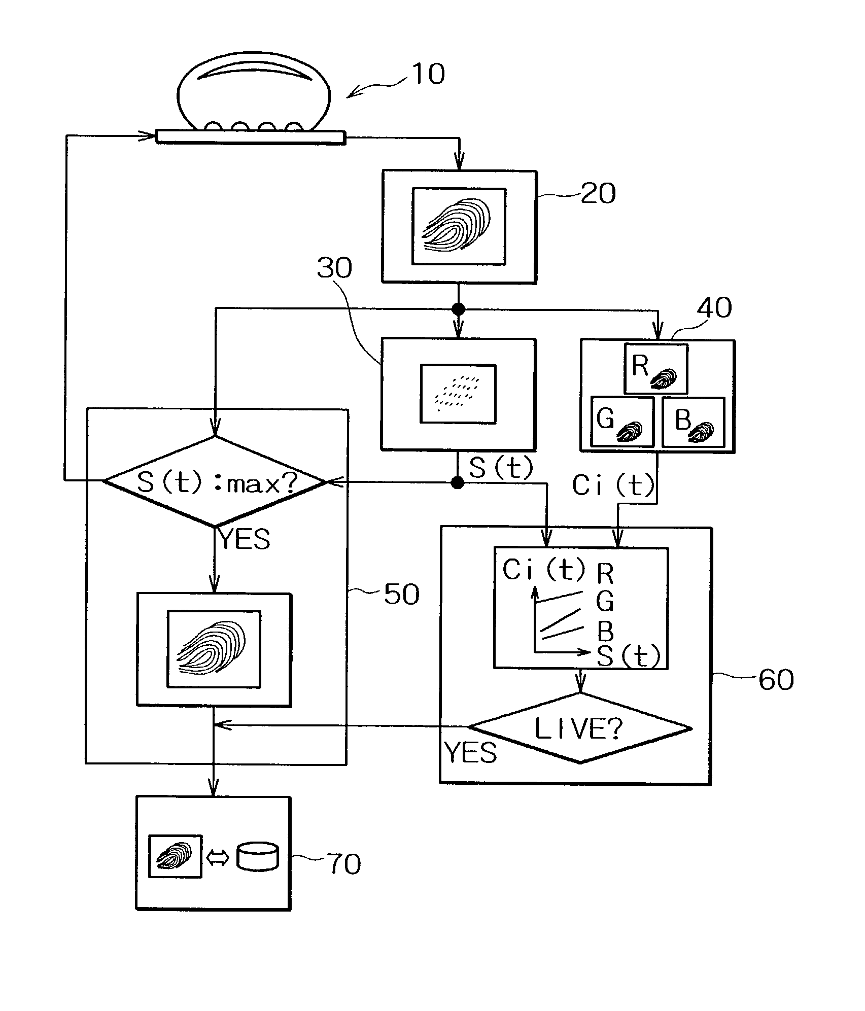
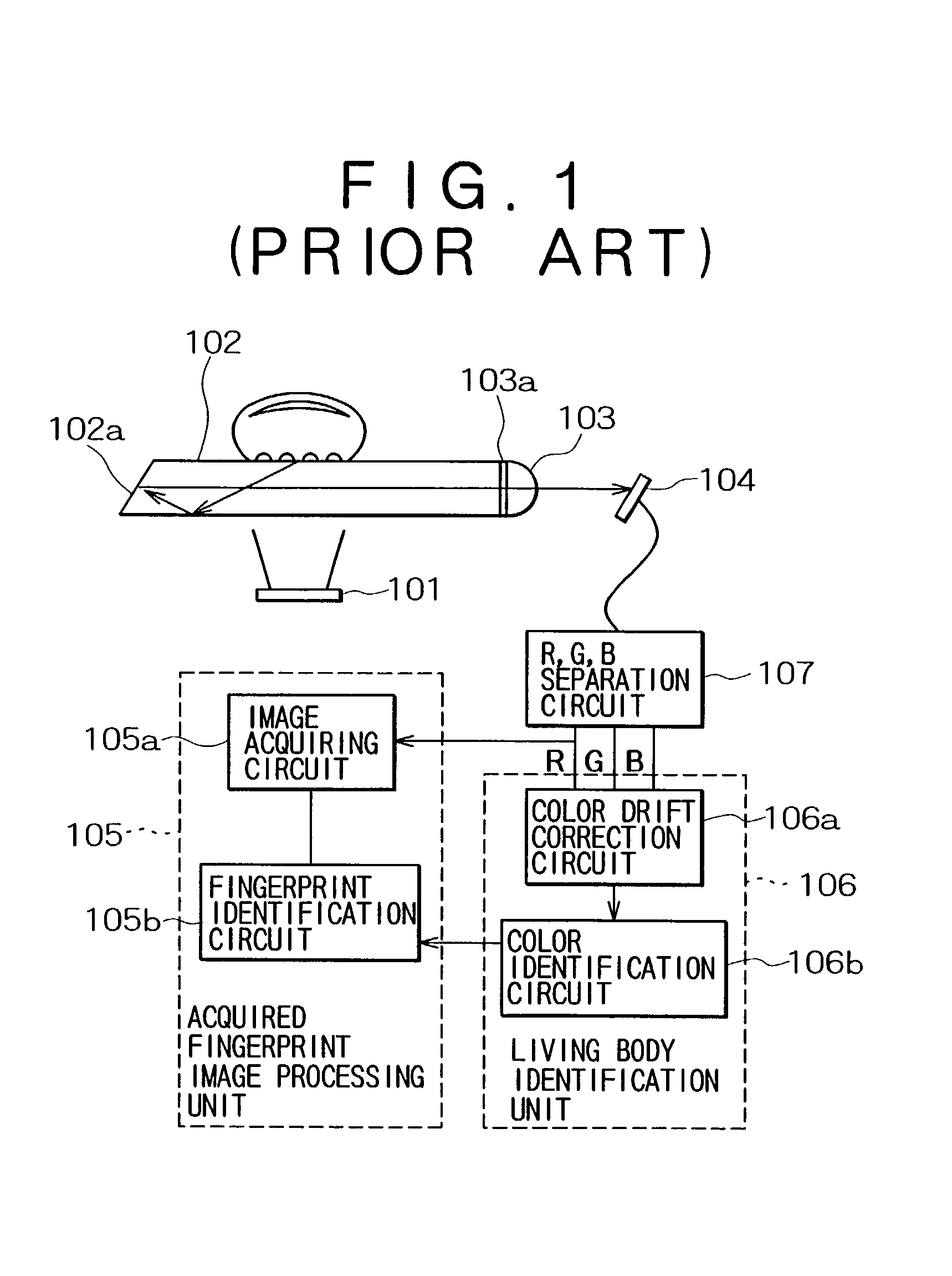
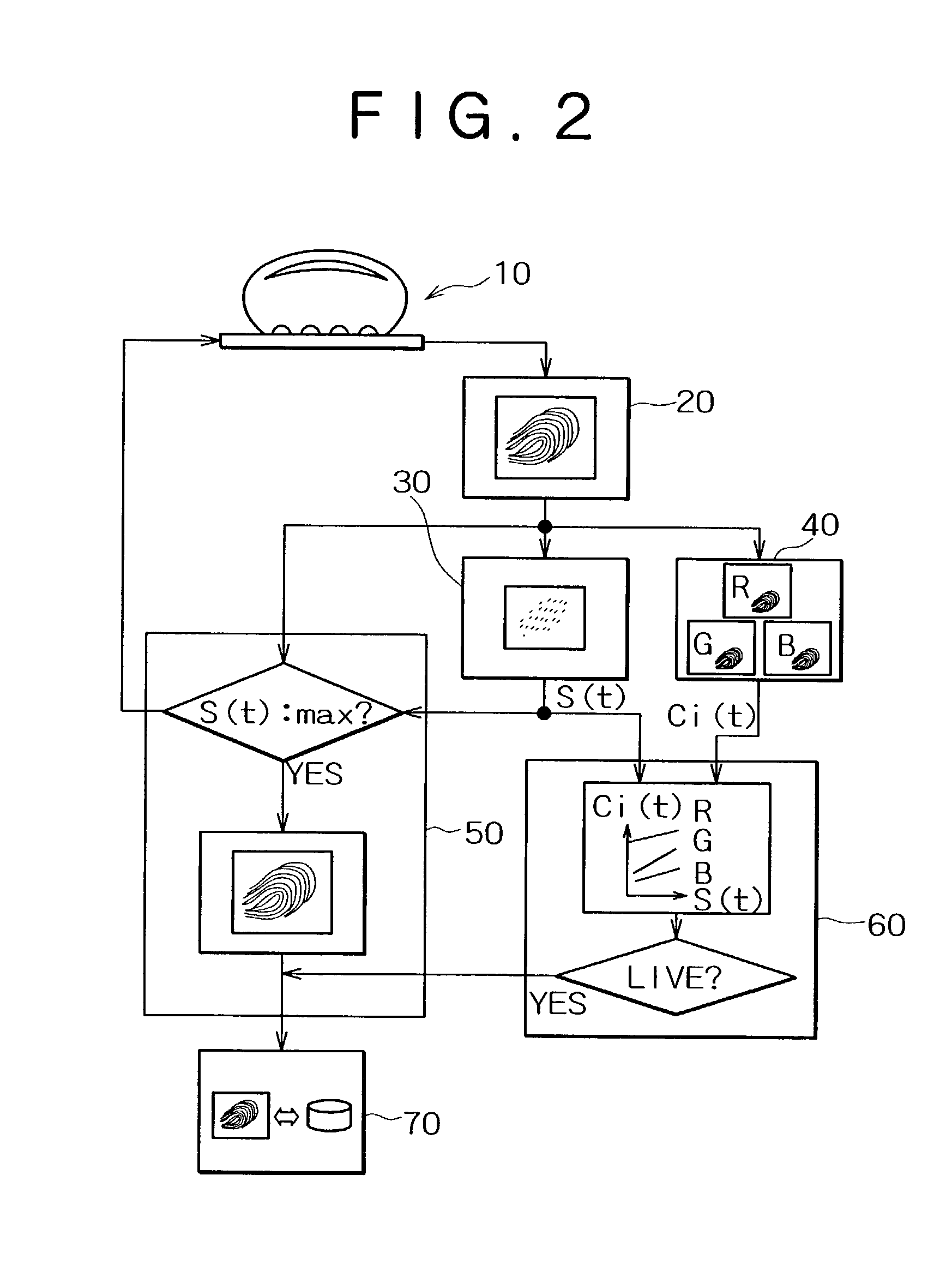
[0078] FIG. 11 is a diagram illustrating the configuration of the present invention. This fingerprint image input device includes a color image sensor 10d, a focusing optical system 11d, a prism 12d, a light source 13d, an image temporary storage unit 20, an areal information extraction unit 30, a color information extracting unit 40, an image storage unit 50, a living body identification unit 60 and a fingerprint identification unit 70.

[0079] The constituent elements of the same functions have the same numerals in FIG. 2 and FIG. 11. What is featured in FIG. 11 is that the color fingerprint image acquiring unit uses the color image sensor 10d, the focusing optical system lid, the prism 12d and the light source 13d. Specifically, the color image sensor 10d may be a color CCD, the focusing optical system lid may be a lens, and the light source 13d may be a white light emitting diode.

[0080] In this configuration that takes advantage of the total internal reflection of light, high cont...

first embodiment

[0087] Third, in the configuration shown in FIG. 2 of the first embodiment, only necessary image data is sent from the image temporary storage unit to the image storage unit. Thus it is not necessary to store all the fingerprint images. As a result, it is possible to prevent the growth of circuit scale for analyzing the series of fingerprint images and to prevent a rise in manufacturing cost.

[0088] While the present invention has been described in some preferred embodiments, it will be apparent to those skilled in the art that the disclosed invention may be modified in numerous ways and may assume many embodiments within the scope of the invention.

[0089] As described so far, the fingerprint image input device and fingerprint-based living body identification method of the invention acquire a plurality of fingerprint images by depressing a finger onto the detector surface and detecting the finger color in synchronization with the acquisition of fingerprint images as well as detecting ...


PUM


Abstract

A color image sensor sequentially acquires a plurality of fingerprint images when a finger is pressed against the detector surface. A color information extraction unit detects the finger color in synchronization with the input of the plurality of fingerprint images. An areal information extraction unit detects a physical quantity representing the pressure applied by the finger to the color image sensor when the plurality of fingerprint images are acquired, particularly, the quantity related with the area of the finger in contact with the detector surface. A living body identification unit determines whether the finger is a live or dead one by the analysis of correlation between the physical quantity and the finger color. According to this configuration, even if the finger color does not change much, it is possible to distinguish living bodies from dead ones if there is a sufficient correlation with information such as the area of the fingerprint that reflects the finger pressure. The thickness of the fingerprint input unit is approximately 1-2 mm, determined by the sum of the thickness of the planar light source and that of the color image sensor.

Description

[0001] 1. Field of the Invention[0002] The invention relates to fingerprint image input devices and living body identification methods using fingerprint images. More specifically, the invention relates to a fingerprint image input device and a living body identification method using fingerprint images that determines whether the finger under scanning is a live or dead one based on the changes in the finger color that changes with the force applied to the finger.[0003] 2. Description of the Related Art[0004] Conventionally, the fingerprint image input device has been used for fingerprint identification and user authentication for computer security and the like. For fingerprint identification, however, the fingerprint image input device is used to identify dead bodies as well as living bodies. Because some fingerprint devices do not distinguish between living bodies and dead ones, they allow an unauthorized access to computers, for example, if someone uses counterfeit goods (replicas)...

Claims


Application Information

Patent Timeline
IPC IPC(8): A61B5/117G01B11/28G01B11/24G06K9/00G06T1/00
CPCG06K9/00067G06K9/00899G06V40/1347G06V40/40
Inventor FUJIEDA, ICHIRO
Owner VISTA PEAK VENTURES LLC
Why Eureka
Try Eureka