Ceramic cutters

a cutter and ceramic technology, applied in the field of ceramic cutters, can solve the problems of defective scoring of certain materials, shortening the service life of the cutting wheel, and affecting the quality of the finished produ

a cutter and ceramic technology, applied in the field of ceramic cutters, can solve the problems of defective scoring of certain materials, shortening the service life of the cutting wheel, and affecting the quality of the finished produ

US20030047056A1Inactive Publication Date: 2003-03-13GERMANS BOADA SA

Image

  • Ceramic cutters
  • Ceramic cutters
  • Ceramic cutters

Examples


Embodiment Construction

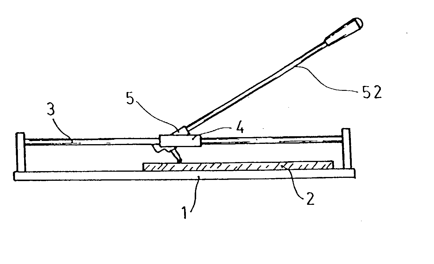
[0009] In order to solve the above mentioned problems, the following improvements have been invented and introduced for ceramic cutting machines, which are the aim of this invention, and are simple in their construction and contribute a series of advantages as far as obtaining a continuous scored line is concerned and a reduction in the vibration transmitted via the cutting-wheel--handle set to the cutter.

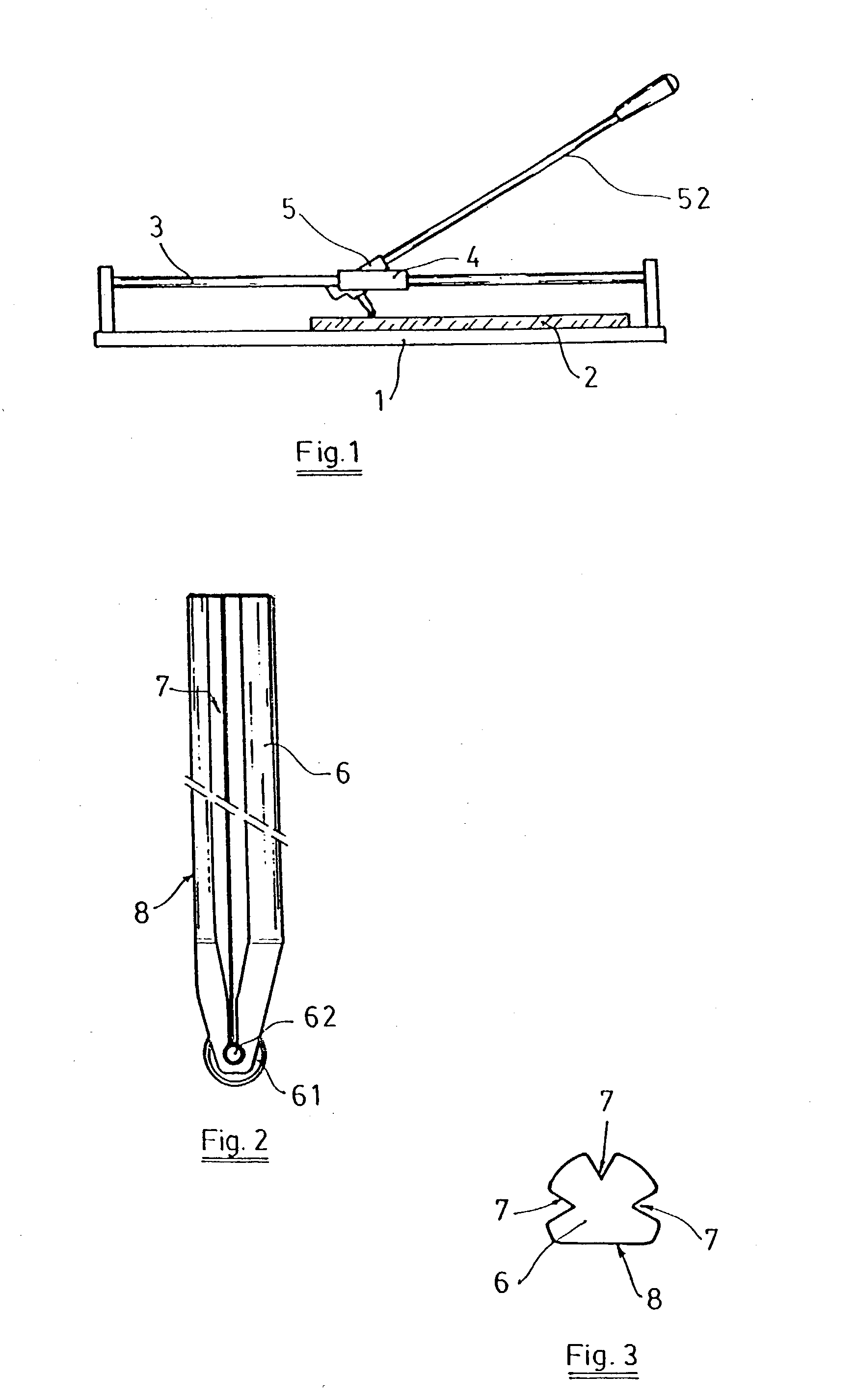
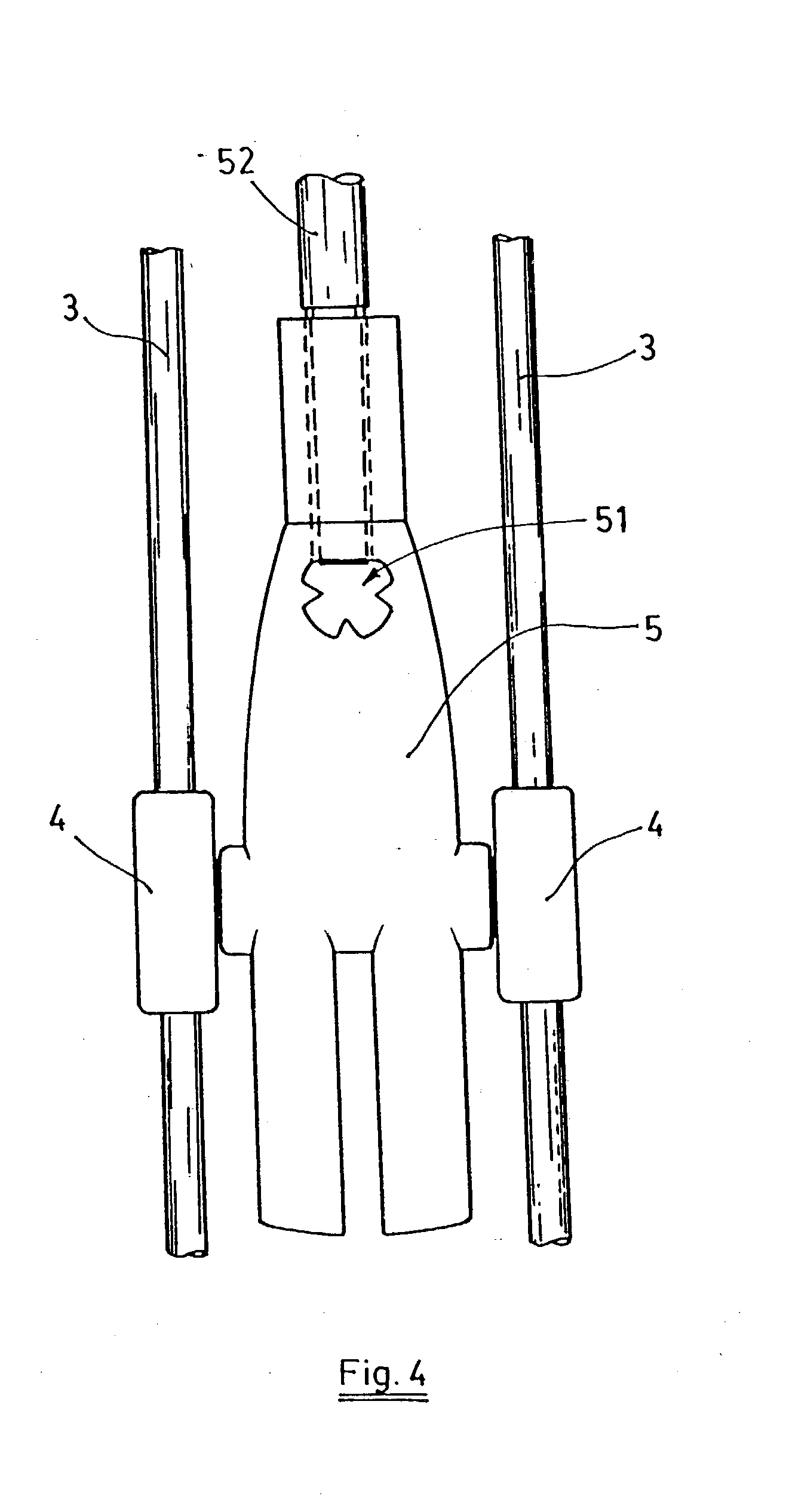
[0010] In accordance with the invention, and being the ceramic cutter of the type that we have previously mentioned, the provision of at least three longitudinal rebates of any geometry in the periphery of the cutting-wheel handle has been made, whose aim is to reduce the frequency of vibration during the scoring process, and, at least one coplanar or rebated longitudinal plane with respect to the general exterior surface of the handle for the actuation of the end of the lever with the job of fixing it to the machine's cutting-wheel handle holder.

[0011] It is noteworthy that the de...


PUM

PropertyMeasurementUnit
frequenciesaaaaaaaaaa
frequencyaaaaaaaaaa
pressureaaaaaaaaaa

Abstract

Said improvements can be used for cutters provided with a base to support the ceramic piece that is to be cut, longitudinal guides for displaceable assembly of a support on which a collapsible cutting wheel holder is mounted, said holder being provided with a threaded hole hole for mounting an actuating lever that makes it possible to press and displace the cutting wheel on the ceramic piece by marking the breaking or cutting line thereof. The periphery of the handle of the cutting wheel has at least three longitudinal grooves having any given geometry with the purpose of reducing the frequency of vibration thereof during grating of the ceramic pieces, and at least one longitudinal plane that is co-planar or projects inward relative to the general outer surface of the handle for actuating the end of the lever intended for the immobilization thereof in the cutting wheel holder.

Description

THE AIM OF THE INVENTION[0001] This invention deals with the improvements made to manually actuated ceramics cutting machines that include the means for the movement of a scoring tool over the ceramic tile defining thereupon the breakage or cutting line.[0002] The improvements mentioned refer basically to the cutting-wheel handle or cutting tool and the corresponding cutting-wheel handle holder.BACKGROUND TO THE INVENTION[0003] Manual ceramics cutters generally consist of a base to support the piece of ceramic to be cut, some longitudinal guides for the movable assembly of a support on which the folding cutting-wheel handle holder is mounted, on which the cutting-wheel handle is fixed, and an actuating lever to press and move the cutting-wheel on the ceramic thus scoring the breakage or cutting line.[0004] The cutting-wheel usually comprises a small cutting disk made of tungsten carbide which is assembled to allow for free rotation on the front end of a handle, the scoring tool conf...

Claims


Application Information

Patent Timeline
13 Mar 2003
Publication
US20030047056A1
IPC
B28D1/22
CPC
B28D1/225; Y10T83/9457; Y10T83/9403; Y10T225/321; Y10T225/325; Y10T83/0385; Y10T83/9377
Inventors
TORRENTS I COMAS, JOSEP