Curb inlet catch basin filter

a filter and inlet basin technology, applied in the field of filters, can solve the problems of affecting the flow rate of sewage, affecting the quality of sewage, and affecting the quality of sewage, and achieve the effect of convenient installation

Inactive Publication Date: 2003-03-13
HARRIS JOHN F +1
View PDF6 Cites 43 Cited by
  • Summary
  • Abstract
  • Description
  • Claims
  • Application Information

AI Technical Summary

Benefits of technology

[0008] Accordingly, our invention provides a filter with a support structure consisting of essentially stationary or immobile parts which filter out storm water pollutants which have entered a curb inlet. This structure easily installs without altering the catch basin.[0009] Several objects and advantages of the present invention are:[0010] a) to provide a curb inlet catch basin with a filter comprising a support structure which is installed in curb inlet basins which does not alter the structural integrity of the inlet catch basin;[0011] b) to provide a curb inlet catch basin with a filter comprising a support structure which is safe and easy to install by hand without the aid of power tools or heavy machinery;[0012] c) to provide a curb inlet basin with a filter comprising a support structure which can be easily adjusted to fit curb inlet catch basins of varying sizes and dimensions;[0013] d) to provide a curb side catch basin with a filter comprising a support structure with no moving mechanical parts and thus essentially not subject to rapid wear, to mechanical failure in a basins' harsh environment including winter freezing.[0014] e) to provide a curb side catch basin with a filter comprising a support structure that does not interfere with the normal flow of street traffic including machinery such as snow plows;[0015] f) to provide a curb inlet basin with a filter comprising a support structure which is not accessible though the curb inlet and thus essentially not subject to vandalism;[0016] g) to provide a curb inlet catch basin with a filter comprising a support structure which positions an absorbent medium within a basin to absorb chemical pollutants for example hydro carbons and oils;[0017] h) to provide a curb inlet catch basin with a filter comprising a support structure that can serve either as a temporary or a permanent Storm Water Pollution Prevention Plan.[0018] Further objects and advantages of the present invention over prior art is that it is a filter containing no moving mechanical parts with a means for either permanent or temporary installation entirely off the street inside a curb inlet catch basin which is inexpensive to manufacture, easy to install and maintain. Further objects and advantages of our invention will also become apparent from consideration of the drawings and ensuing descriptions of it.[0019] In the drawings, closely related figures have the same number but different alphabetical suffixes.[0020] FIG. 1 is a top perspective view of our filter with a support structure and a bag assembly installed in a typical curb inlet catch basin.[0021] FIG. 2 is a side view of our complete filter installed in the curb inlet catch basin.[0022] FIG. 3 is a side view of our filters' support structure inside the curb inlet catch basin.[0023] FIG. 4 is a top view of our complete filter installed in a curb inlet catch basin.2

Problems solved by technology

These devices often cause obstructions in the street and are subject to vandalism.
These do not filter out smaller pollutants or provide a means to retain these pollutants off site of the street.
This debris however, then backs up into the street.
But this provides no off street containment of debris which then accumulates in the street up stream from the curb inlet.
The capacity of the basket is small and limited in size.
The device does not have a means to convey the storm water from the inlet floor to the basket interior.
This is subject to vandalism and expensive to install.
Other prior art is unnecessarily complex.
This comprises an unnecessarily complex bypass means.
The bypass is a moving part which is subject to wear, and to jamming open with debris.
During the winter the movable part can also freeze into position and cause the system to either not filter or back up storm water into the street.
The hinged and spring loaded by pass means is unnecessarily expensive to manufacture.
This mounting structure is unnecessarily expensive to manufacture to install and to remove.
The apparatus also has no on job sight adjustment provision to accommodate the various sizes of curb catch basins which are regularly encountered in the field.

Method used


Image

  • Curb inlet catch basin filter
  • Curb inlet catch basin filter
  • Curb inlet catch basin filter

Examples


Embodiment Construction

. 1-4

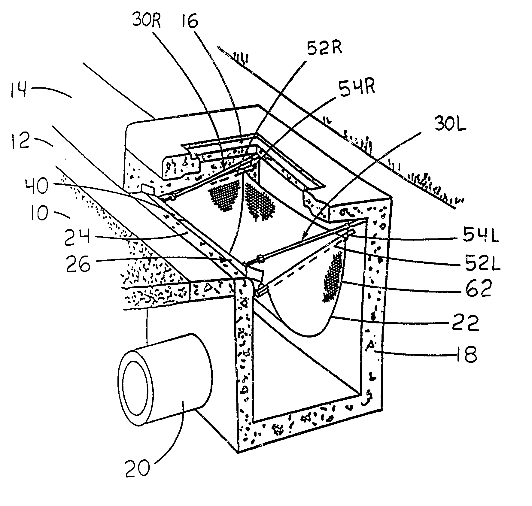
[0024] FIG. 1 best shows our installed invention in relationship to its typical surroundings. A curb inlet catch basin 18 is located down stream from a street 10 and a gutter 12 and parallel with a curb 14. A catch basin outlet 20 extends away from the basin 18 The invention comprises a bag assembly 22, and a support structure 26.

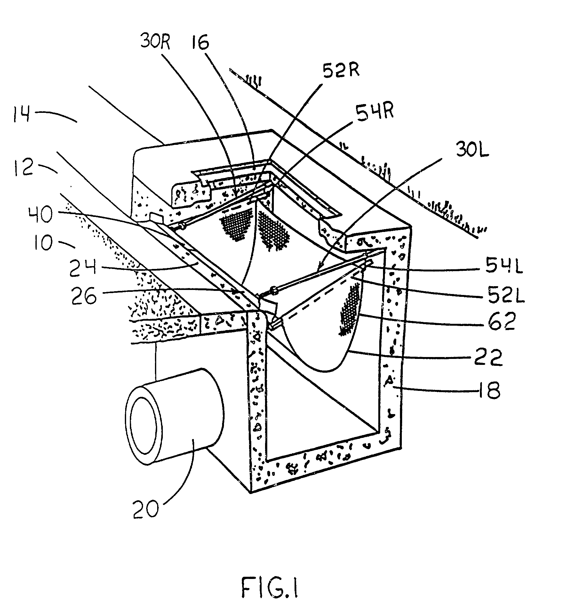
[0025] The bag assembly shown in FIGS. 1,2,3,4 is best shown in FIG. 4. The bag assembly comprises a filter basket 22 and two insert rods 54R and 54L. The basket is made of filter material with hydraulic openings smaller than the pollutants intended to be filtered from the storm water. This material allows the storm water to pass through while blocking various sizes of pollutants. The bag assembly is preferably made from a polypropylene geotextile fabric. However this filter may be made of many types of materials for example; cotton or burlap fabric or stainless, fiberglass or aluminum screen.

[0026] The position of the bag assembly inside the basin is ...


PUM

PropertyMeasurementUnit
pressuresaaaaaaaaaa
gravityaaaaaaaaaa
pressureaaaaaaaaaa

Abstract

This invention is a filter for a street curb inlet catch basin that comprises a removable filter basket assembly, a funnel to channel storm water into the basket, and a support structure that holds the filter in place within the basin by means of bracing the structure against the basins interior walls without altering the interior walls of the basin.

Description

REFERENCES CITED[0001] U.S. Patent Documents:1 References Cited U.S. Pat. Documents: 4,594,157 Jun. 10, 1986 McGowan 5,403,474 Apr. 4, 1995 Emery 5,575,925 Nov. 19, 1996 Logue Jr. 5,954,952 Sep. 21, 1999 Strawser, Sr. 6,015,489 Jan. 18, 2000 Allen et al. 6,106,706 Aug. 22, 2000 Roy et al.OTHER REFERENCES[0002] Drain Pack.TM.DESCRIPTION OF THE PRIOR ART[0003] This invention relates to a filter with a support structure for placing a filter inside of a street curb inlet catch basin below and down stream from the basins' curb inlet.[0004] The inlet is typically in the curb of a street. Storm water flows off the street, down the gutter, through the curb inlet, then into the catch basin, and out the basin outlet. Before the ground water flows into a sewer line it needs to be filtered as free of pollutants as possible. These pollutants may include large debris such as sticks and leaves as well as soil.[0005] In the past this filtration has been accomplished by placing a filter means in the...

Claims


Application Information

Patent Timeline
Patent Type & Authority Applications(United States)
IPC IPC(8): B01D29/01E03F1/00
CPCB01D29/014E03F1/00E03F5/0404B01D29/27
Inventor HARRIS, JOHN F.PAGE, ARDLE E.
Owner HARRIS JOHN F
Why Eureka
Try Eureka