Metal coordination compound, luminescence device and display apparatus

a technology of luminescence device and coordination compound, which is applied in the direction of group 3/13 element organic compound, group 5/15 element organic compound, natural mineral layered product, etc., can solve the problems of reducing stability, deteriorating luminescence, and lowering the resultant luminescence efficiency

Inactive Publication Date: 2003-03-20
CANON KK
View PDF3 Cites 174 Cited by
  • Summary
  • Abstract
  • Description
  • Claims
  • Application Information

AI Technical Summary

Problems solved by technology

However, the above-mentioned organic EL devices utilizing phosphorescence have accompanied with problems of a lower luminescence efficiency and stability thereof (luminescent deterioration) particularly in an energized state.
This is because the longer phosphorescence life increases molecules placed in their triplet excited state which is a waiting state for phosphorescence, thus lowering the resultant luminescence efficiency partic

Method used


Image

  • Metal coordination compound, luminescence device and display apparatus
  • Metal coordination compound, luminescence device and display apparatus
  • Metal coordination compound, luminescence device and display apparatus

Examples


example 3

[0161] A simple matrix-type organic EL device shown in FIG. 2 was prepared in the following manner.

[0162] On a 1.1 mm-thick glass substrate 21 (75.times.75 mm), a ca. 100 nm-thick transparent electrode 22 of ITO (as an anode) was formed by sputtering, followed by patterning in a stripe form comprising 100 lines (each having a width of 100 .mu.m and a spacing of 40 .mu.m).

[0163] On the ITO electrode 22, an organic lamination layer 23 including four organic layers was formed in the same manner as in Example 1.

[0164] Then, on the organic lamination layer 23, a metal electrode comprising a 10 nm-thick Al--Li alloy layer (Li: 1.3 wt. %) and a 150 nm-thick Al layer (disposed on the Al--Li alloy layer) was formed by vacuum deposition (2.7.times.10.sup.-3 Pa (=2.times.10.sup.-5 Torr)) with a mask, followed by patterning in a stripe form comprising 100 lines (each having a width of 100 .mu.m and a spacing of 40 .mu.m) arranged to intersect the ITO stripe electrode lines at right angles, thus...

example 4

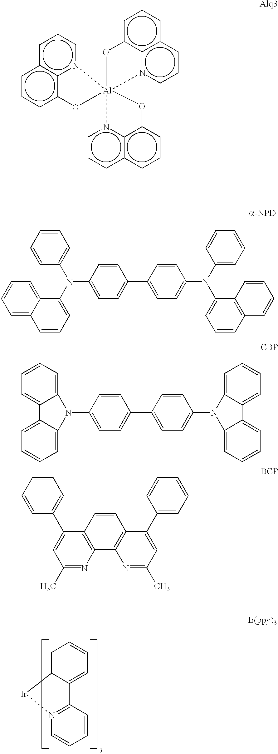
[0167] An organic EL device was prepared in the same manner as in Example 1 except that the metal coordination compound (Ex. Comp. No. 37) was charged to a metal coordination compound of the formula 41 (specifically shown hereinabove).

[0168] When the EL device was supplied with a voltage of 20 volts, stable and high-efficiency yellowish green luminescence resulting from the thienylpyridine ligand of the metal coordination compound of the formula 41 was confirmed. The luminescence was stable even when the EL device was continuously driven for 100 hours.

example 5

[0169] An organic EL device was prepared in the same manner as in Example 1 except that the metal coordination compound (Ex. Comp. No. 37) was charged to a metal coordination compound of the formula 44 (specifically shown hereinabove).

[0170] When the EL device was supplied with a voltage of 20 volts, stable and high-efficiency reddish orange luminescence resulting from the metal coordination compound of the formula 44 was confirmed. The luminescence was stable even when the EL device was continuously driven for 100 hours.


PUM

PropertyMeasurementUnit
Nanoscale particle sizeaaaaaaaaaa
Structureaaaaaaaaaa

Abstract

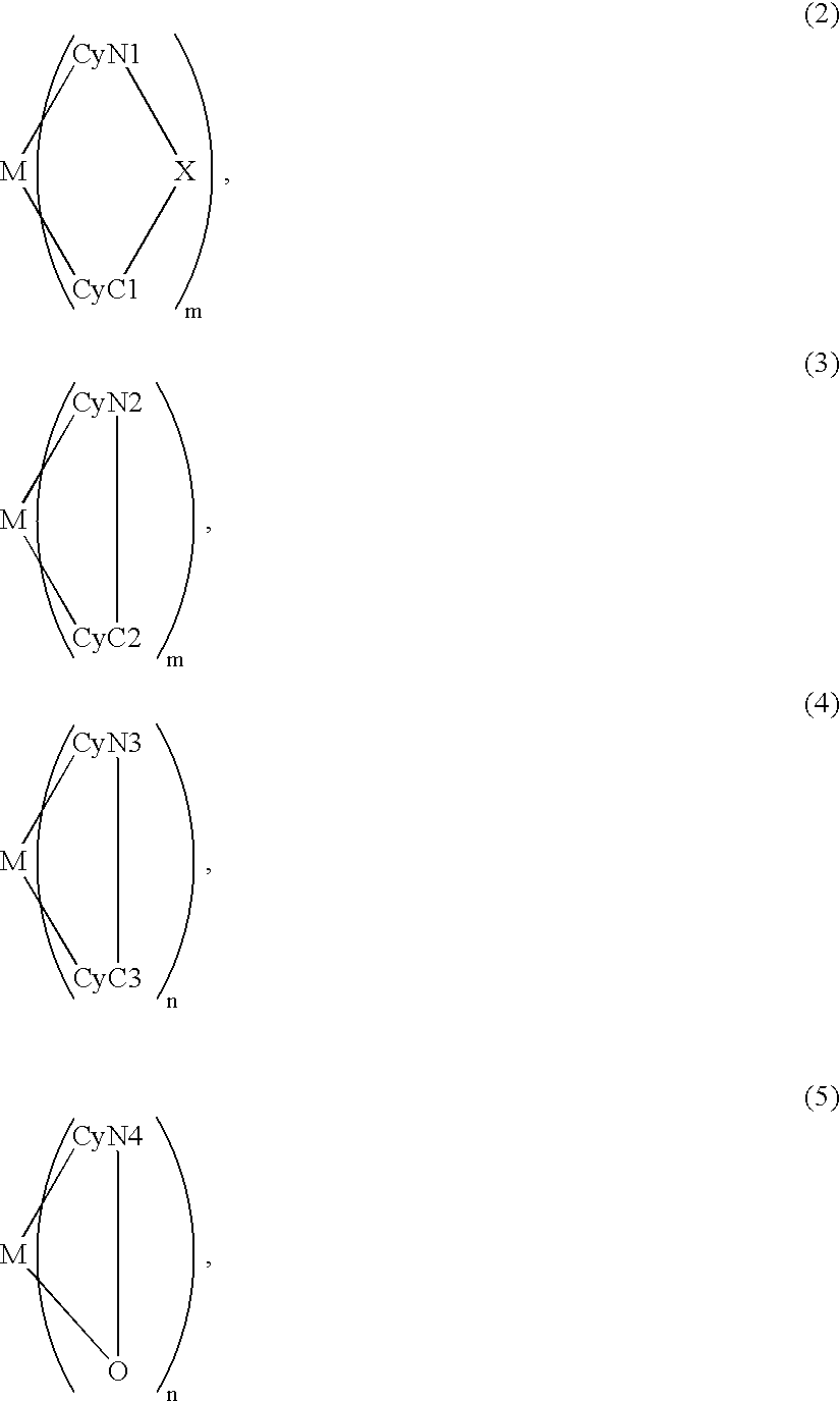
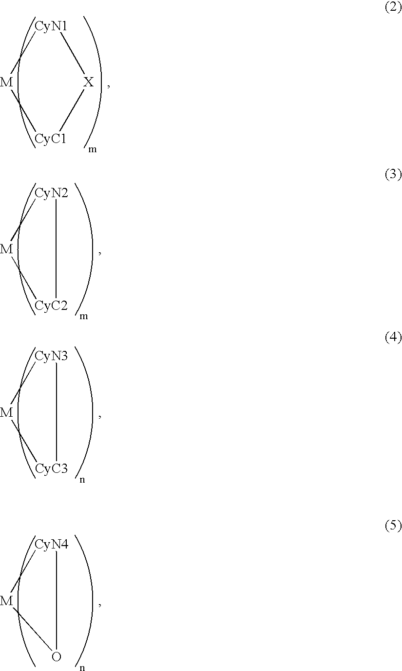
An organic EL device includes a luminescence layer containing, as a luminescent material allowing a high-luminescence and high-efficiency luminescence for a long period of time, a metal coordination compound represented by the following formula (1): LmML'n, wherein M denotes Ir, Pt, Ph or Pd; L denotes a bidentate ligand; L' denotes a bidentate ligand different from L; m is an integer of 1, 2 or 3; and n is an integer of 0, 1 or 2 with the proviso that the sum of m and n is 2 or 3. The partial structure MLm is represented by a formula (2) or a formula (3) shown below, and the partial structure ML'n is represented by a formula (4) or a formula (5) shown below: wherein CyN1, CyN2 and CyN3 independently denote a substituted or unsubstituted cyclic group containing a nitrogen atom connected to M; CyN4 denotes a cyclic group containing 8-quinoline or its derivative having a nitrogen atom connected to M; CyC1, CyC2 and CyC3 independently denote a substituted or unsubstituted cyclic group containing a carbon atom connected to M, with the proviso that the metal coordination compound is represented by the formula (2) when n is 0.

Description

FIELD OF THE INVENTION AND RELATED ART[0001] The present invention relates to a metal coordination compound, an organic luminescence device using the metal coordination compound and a display apparatus using the device. More specifically, the present invention relates to an organic metal coordination compound having a formula (1) appearing hereinafter as a luminescence material so as to allow stable luminescence efficiency, an organic luminescence device using the metal coordination compound and a display apparatus including the luminescence device.[0002] An organic electroluminescence (EL) device has been extensively studied as a luminescence device with a high responsiveness and high efficiency.[0003] The organic EL device generally has a sectional structure as shown in FIG. 1A or 1B (e.g., as described in "Macromol. Symp.", 125, pp. 1-48 (1997)).[0004] Referring to the figures, the EL device generally has a structure including a transparent substrate 15, a transparent electrode 1...

Claims


Application Information

Patent Timeline
IPC IPC(8): C07D213/06C07D213/50H01L51/50C07D213/64C07D215/24C07D409/04C07F15/00C09K11/06H01L51/00H01L51/30
CPCC07F15/0033C07F15/006C07F15/0073C07F15/0086H01L51/0042H01L51/0085H01L51/0087H01L51/009H01L51/5016Y10S428/917H10K85/146H10K85/361H10K85/346H10K85/342H10K50/11H10K2101/10C09K11/06
Inventor TSUBOYAMA, AKIRAMIZUTANI, HIDEMASAOKADA, SHINJIROTAKIGUCHI, TAKAOMIURA, SEISHINOGUCHI, KOJIMORIYAMA, TAKASHIIGAWA, SATOSHIKAMATANI, JUNFURUGORI, MANABU
Owner CANON KK
Why Eureka
Try Eureka