Magnetron drive circuit

a drive circuit and magnetic field technology, applied in the direction of pulse generators, pulse techniques, instruments, etc., can solve the problems of inability to generate transmission pulses, inability to reduce the resistance value of absorption resistors to a large extent, and inability to obtain so as to reduce the resistance value of absorption resistors, sharp falling edge of transmission pulses, and the effect of sharp falling edg

Inactive Publication Date: 2003-03-27
FURUNO ELECTRIC CO LTD
View PDF0 Cites 11 Cited by
  • Summary
  • Abstract
  • Description
  • Claims
  • Application Information

AI Technical Summary

Benefits of technology

0022] Since the residual energy absorption circuit efficiently absorbs the residual energy left in the pulse transformer, it is possible to make the falling edge of the transmission pulse sharper than that obtained with the prior art.
0023] In still another aspect of the invention, a magnetron drive circuit comprises a residual energy absorption circuit for absorbing residual energy left in a pulse transformer for generating a magnetron driving pulse to eliminate the need for an absorption resistor conventionally connected between both ends of a primary winding of the pulse transformer for absorbing the residual energy left in the pulse transformer.
0024] The conventional ab

Problems solved by technology

If the rising edge of a pulse for driving the magnetron is made too sharp to obtain a narrow pulselength, the magnetron will fail to oscillate, resulting in an inability to generate the transmission pulse.
The conventional absorption resistor connected between both ends of the primary wi

Method used


Image

  • Magnetron drive circuit
  • Magnetron drive circuit
  • Magnetron drive circuit

Examples


first embodiment

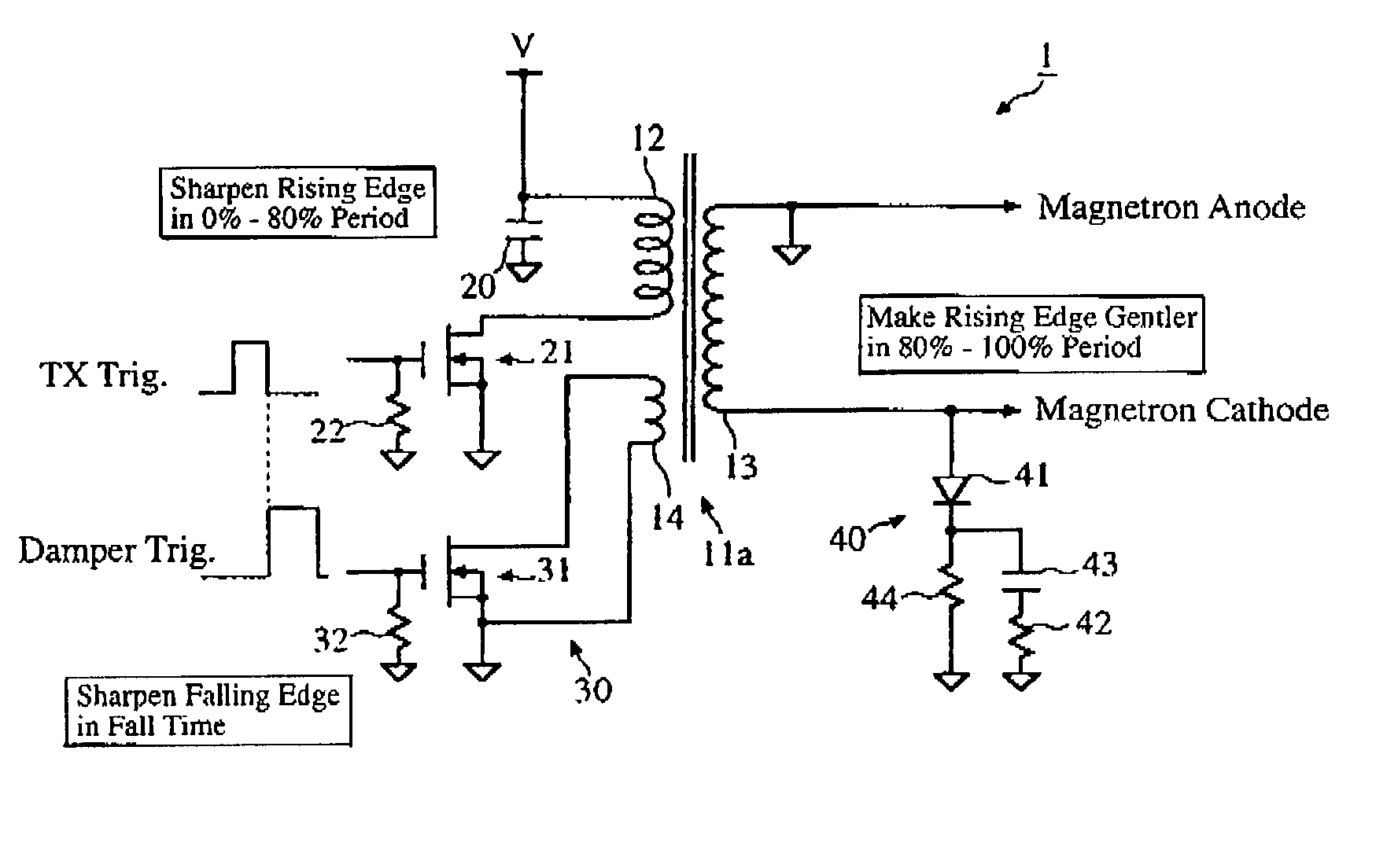
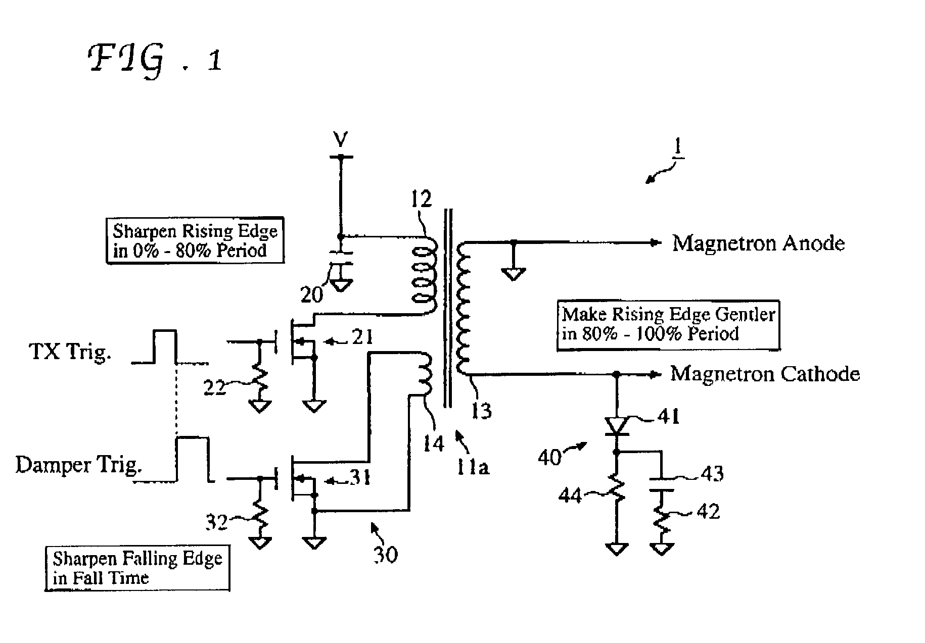
[0036] The magnetron drive circuit 1 of the first embodiment invention is now described in more detail referring to the drawings. As stated above, the magnetron drive circuit 1 is provided with the active damper circuit 30 and the nonlinear load circuit 40 connected to the pulse transformer 11a, which includes a primary winding 12 and the aforementioned secondary winding 13 and auxiliary winding 14.

[0037] One end of the primary winding 12 is connected directly to a power source V and grounded through a capacitor 20 while the other end of the primary winding 12 is connected to a drain of a switching FET (NMOSFET) 21. A source of the switching FET 21 is directly grounded and its gate is grounded through a resistor 22. On the other hand, one end of the secondary winding 13 of the pulse transformer 11a is connected to a cathode of the magnetron (not shown) while the other end of the secondary winding 13 is connected to an anode of the magnetron.

[0038] The active damper circuit 30 includ...

second embodiment

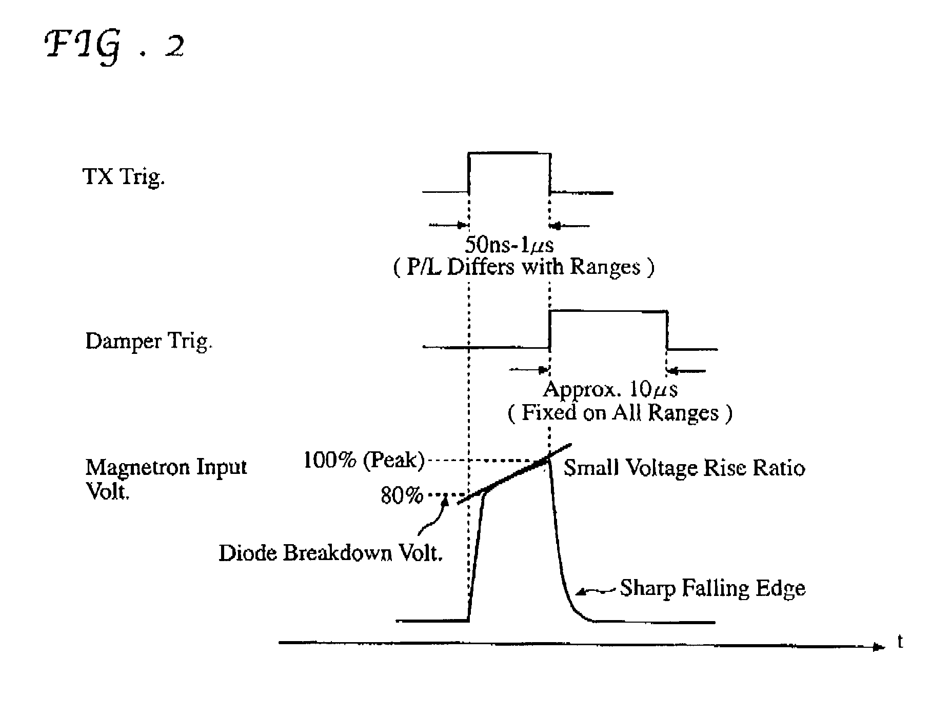
[0056] FIG. 6 is a diagram showing the waveforms of input and output pulses of the magnetron drive circuit 1 of the When a transmission trigger and a damper trigger shown in FIG. 6 are fed into the magnetron drive circuit 1, it outputs a narrow transmission pulse having a generally rectangular waveform with sharply shaped rising and falling edges. The transmission trigger (transmission pulse) is made to have a generally rectangular waveform with the top portion thereof gradually increasing as shown in FIG. 6. In a pulse radar, the pulselength of the transmission pulse is normally varied with range scales. As an example, the pulselength may be selected within a range of 50 ns to 1 .mu.s. When the rectangular transmission trigger is fed into the switching FET 21 of the magnetron drive circuit 1, magnetron input voltage produced at the secondary winding 13 is made to have a generally rectangular waveform with sharply shaped rising edge and a sharply shaped falling edge because of the ...


PUM


Abstract

The invention provides a magnetron drive circuit which drives a magnetron to produce a generally rectangular-shaped narrow transmission pulse having sharply shaped rising and falling edges. The magnetron drive circuit includes a nonlinear load circuit and an active damper circuit. The nonlinear load circuit becomes on at around 80% of a peak output voltage of a pulse transformer (at which the magnetron begins to oscillate) is connected to a secondary winding of the pulse transformer in parallel with the magnetron. The active damper circuit absorbs residual energy left in the pulse transformer without any need for an absorption resistor conventionally connected between both ends of a primary winding of the pulse transformer.

Description

[0001] 1. Field of the Invention[0002] This invention relates to a drive circuit for a magnetron used in a pulse-modulated radar, for example.[0003] 2. Description of the Prior Art[0004] A pulse-modulated radar (hereinafter referred to simply as the pulse radar) is a radar which determines the distance to a target from the time that elapses after transmitting pulsed waves toward the target before a portion of the pulsed waves reflected by the target is received. Given the velocity of light, c, and the elapsed time .DELTA.t between transmission and reception, the distance D to the target is calculated as follows:D=c.DELTA.t / 2[0005] Important factors for judging the performance of the pulse radar are such characteristics as bearing discrimination, maximum and minimum detecting ranges, as well as range discrimination. The range discrimination is defined as a minimum distance R at which two targets placed on the same bearing with respect to a radar antenna can be displayed separately. S...

Claims


Application Information

Patent Timeline
IPC IPC(8): H03K3/53G01S7/282H03K5/12
CPCG01S7/282H01J2225/50H03K5/12H03K3/57
Inventor KITABATAKE, ASAOFUNAE, AKIO
Owner FURUNO ELECTRIC CO LTD
Why Eureka
Try Eureka