Offloading arrangements for speard moored FPSOs

a technology of fpsos and mooring, which is applied in the direction of passenger handling apparatus, transportation and packaging, vessel construction, etc., can solve the problems of inability to weathervane, the magnitude of potential damage, and the cost of maintaining the shuttle tanker within the safe unloading zone, so as to reduce the risk of collision

Inactive Publication Date: 2003-04-03
SOFEC
View PDF17 Cites 28 Cited by
  • Summary
  • Abstract
  • Description
  • Claims
  • Application Information

AI Technical Summary

Benefits of technology

[0018] Another object of the invention is to provide a single point mooring (SPM) for a shuttle tanker where the SPM is controlled directly or indirectly by linkage to a spread moored FPSO, with the result that the disadvantages identified above are overcome.
[0021] Another object of the invention is to provide a mooring system by which a shuttle tanker is moored at one end to a hold back buoy which is indirectly linked to the FPSO by means of a tension member connected between an end of the FPSO and an opposite end of the shuttle tanker, such that the shuttle tanker (1) can move in an arc about the end of the FPSO (2) is prevented from contacting the FPSO by the hold back buoy and (3) can be quickly disconnected from the hold back buoy.
[0028] A fourth offloading arrangement moors a shuttle tanker to a spread moored FPSO in deep water by locating a Single Point Buoy (SPM) a sufficient distance from the FPSO / SPM such that the shuttle tanker is permitted to weathervane 360 degrees about the SPM. The SPM can be moored by diverging hold-back mooring legs, or even a single hold-back leg, to ensure its minimum spacing with respect to the FPSO. The SPM is typically a buoyant column having its upper end provided with a loading boom or turntable for controlled support and positioning of the offloading hose or hoses through a rotatable coupling and the connection thereof to the fluid handling manifold of the shuttle tanker. A connection chain or other suitable connector links the SPM to the FPSO and maintains the position of the buoy or column and provides protection for an offloading riser between the FPSO and the shuttle tanker. The chain and riser have sufficient catenary shapes to permit the shuttle tanker to pass over them without any potential for contact or interference.
[0030] For stationing of SPM buoys relative to a moored FPSO, without using hold-back mooring or anchoring systems for the buoys, one or more dynamic positioning buoys, referred to here as DP buoys, are indirectly linked to the FPSO. According to the sixth offloading arrangement of the present invention, a DP buoy having independent on-board power systems and rotatable hawser and hose turntables is controlled directly on the DP buoy or is remotely controlled by the FPSO. A DP buoy may be stationed at a minimum distance (e.g., about 600 meters) from the FPSO that is sufficient to permit substantially 360 degrees rotation of the shuttle tanker about the DP buoy. Likewise, the DP buoy can be operated to be stationed at any location within an arc of about 180 degrees from the point of connection of its catenary mooring tether, line or chain, with the FPSO as urged by the action of wind, waves or currents. The catenary of the mooring line or chain permits the shuttle tanker to pass over it without contact by the shuttle tanker. A flow line or hose extends from the FPSO along the length of the mooring line or chain to the DP buoy and is protected against excess tension force by the mooring line or chain, because the chain is shorter than the flowline. When offloading of a shuttle tanker is not in progress or is imminently expected, the thrusters of the DP buoy can be deenergized, in which case the weight of the mooring line or chain and offloading hose draws the DP buoy to a rest station close to the FPSO. To provide for protection of the FPSO and the DP buoy when the buoy is located at its close-in rest station, the buoy is provided with one or more fenders. The fenders also provide protection for the shuttle tanker in the event of contact with the buoy.
[0035] FIGS. 3A and 3B are side elevation and plan views of a spread moored FPSO with a shuttle tanker having a hold-back buoy provided to reduce collision risk between the shuttle tanker and the FPSO and to permit environmental compliant lateral excursion of the shuttle tanker with regard to the tension being applied by a traction winch of the FPSO, and

Problems solved by technology

(1) The limited sector available to the shuttle tanker for unloading at the bow or stem of the vessel (centerline dead astern or dead ahead to .+-.30 degrees to port or starboard).
(2) The proximity between the shuttle tanker and the FPSO required for tandem offloading, during approach and offloading with the possibility of collision in severe weather.
(3) The FPSO's inability to weathervane.
(4) The magnitude of potential damage in the event of collision.
(5) The cost of maintaining the shuttle tanker within the safe unloading zone during offloading.
(6) The cost of assisting the shuttle tanker during approach to the FPSO.
Summing up, prior offloading systems and methods for tandem offloading from a spread moored vessel to a shuttle tanker results in collision risk and unloading downtime risk.
Unfortunately, in deep water, the cost of the mooring system, SPM terminal, and the fatigue resistant flow line from the FPSO to the FTB is very high and justified only for installations with high throughput and consequent high frequency of offloading with resulting higher risk.

Method used


Image

  • Offloading arrangements for speard moored FPSOs
  • Offloading arrangements for speard moored FPSOs
  • Offloading arrangements for speard moored FPSOs

Examples


Embodiment Construction

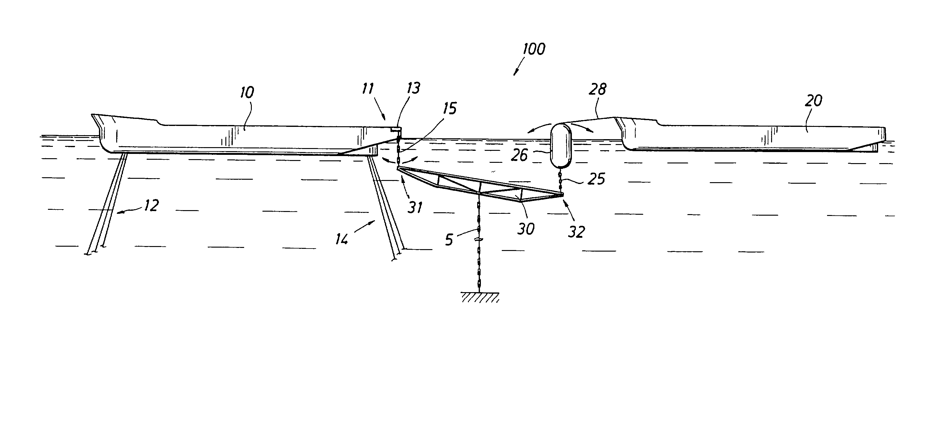
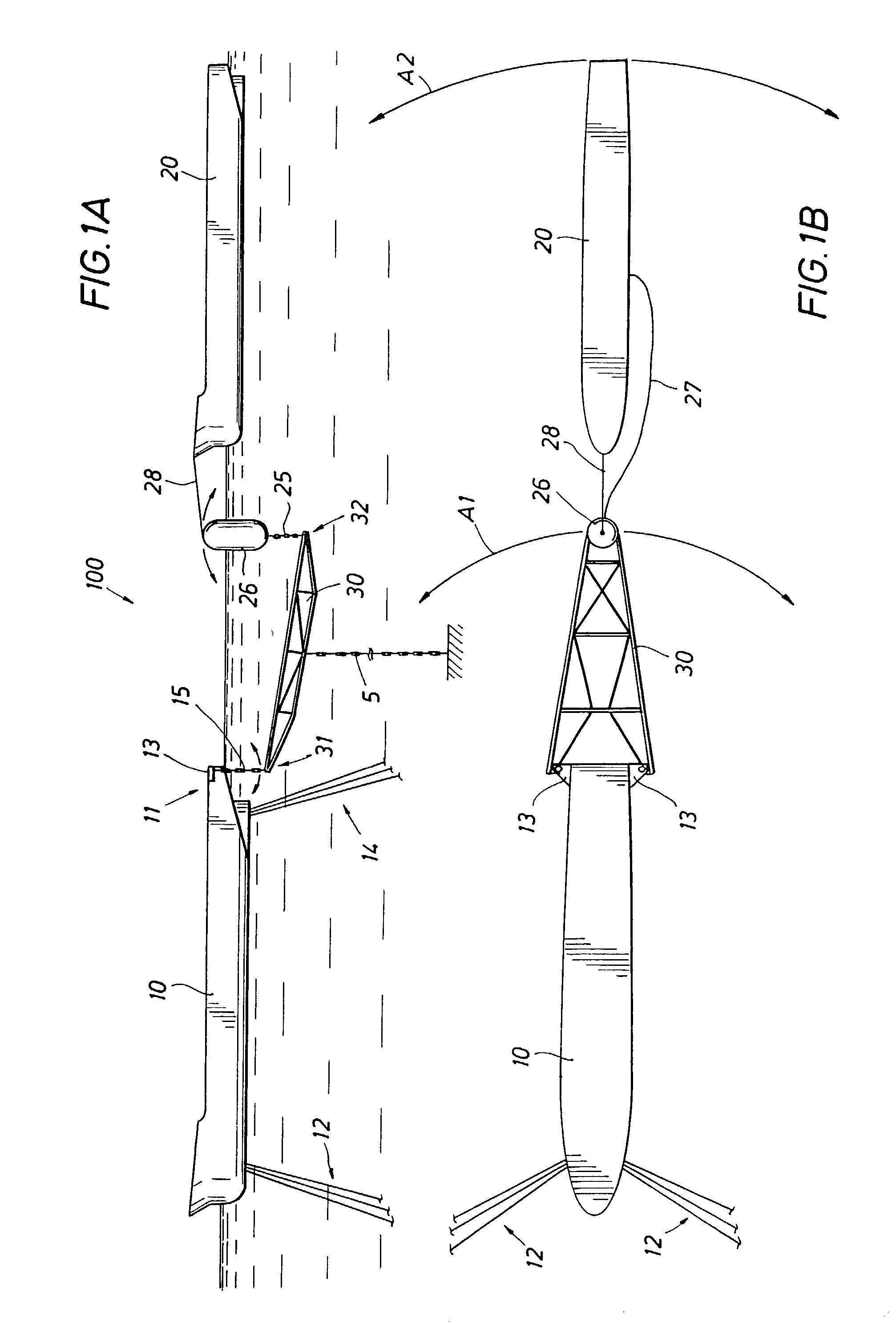
[0043] As illustrated in FIGS. 1A, 1B, a mooring arrangement 100 is illustrated where a submerged yoke 30 is hung from outriggers 13 located at the unloading end 11 of an FPSO, in a pendular fashion, and is supported at its opposite end by a fendered SALM 26. A shuttle tanker 20 is moored to the SALM 26 by a mooring hawser 28 and loaded in the normal fashion through a floating hose 27 between the SALM 26 and a loading manifold of the shuttle tanker 20. The FPSO's aft mooring legs 14 are keel mounted to avoid interference with the yoke 30 during partial weathervaning.

[0044] The submerged yoke 30 is preferably supported at the aft end of the FPSO by two vertical links 15 such as chains or other tension members. Links 15 are connected to outrigger porches 13 and allow the yoke 30 to twist about the end of the FPSO such that fendered SALM 26 can rotate in an arc A1 during weathervaning conditions operating on shuttle tanker 20. The shuttle tanker 20, connected to SALM 26 by the mooring ...


PUM


Abstract

A mooring arrangement between a floating storage body spread moored in deep water and a shuttle tanker, the arrangement including a single point buoyant member that is adapted for mooring a shuttle tanker in offloading position relative to a floating production, storage and offloading vessel (FPSO) with a link between the floating storage body and the single point buoyant member. One embodiment (100) of the invention employs a submerged yoke (30), having one end (31) rotatably coupled to a FPSO (10) and a second end (32), supported by a buoy. A mooring hawser (28) extends from the buoy to the shuttle tanker and product hoses connect the shuttle tanker with the FPSO and extend along the submerged yoke. In another embodiment, the mooring buoy is stationed by a hold-back mooring system (303-304) and the FPSO or the tanker or both is provided with traction devices (308) to move the tanker into loading position with respect to the FPSO. Other embodiments of the invention establish mooring of a shuttle tanker so that it can weathervane 360 degrees during offloading activity. In another embodiment, the mooring buoy (600) is provided with a dynamic positioning system (614) for controlling shuttle tanker positioning with respect to conditions of the environment or for moving the tanker to a desired position during loading.

Description

[0001] This application claims the benefit of U.S. Provisional Patent Application Serial No. 60 / 309,853, filed Aug. 3, 2001 by Roy H. Cottrell, Rick A. Hall, Brent A. Salyer, Caspar N. Heyl and Richard H. Gunderson and entitled "Offloading Arrangements and Methods For Spread Moored FPSOs", which provisional application is incorporated by reference herein for all purposes.[0002] 1. Field of the Invention[0003] This invention relates generally to mooring systems for offshore terminals and in particular to offloading apparatus and methods for spread moored FPSOs (floating production storage and offloading vessels).[0004] 2. Description of the Prior Art[0005] The spread mooring of FPSO vessels with offloading by tandem connection of a shuttle tanker is well-known in the prior art. Prior art tandem connection of a shuttle tanker to an FPSO for hydrocarbon offloading are characterized by several problems:[0006] (1) The limited sector available to the shuttle tanker for unloading at the bo...

Claims


Application Information

Patent Timeline
Patent Type & Authority Applications(United States)
IPC IPC(8): B63B21/50B63B27/24
CPCB63B27/24B63B21/50
Inventor COTTRELL, ROY H.HALL, RICK A.SALYER, BRENT A.HEYL, CASPAR N.GUNDERSON, RICHARD H.
Owner SOFEC
Why Eureka
Try Eureka