Diaphragm, flat-type acoustic transducer, and flat-type diaphragm

a technology of acoustic transducers and diaphragms, which is applied in the direction of diaphragms, transducer details, electrical transducers, etc., can solve the problems of complex investigation of the portion at which the connection failure has occurred, complex handling of cases, and complex investigation of the fault of the connection

Inactive Publication Date: 2003-04-10
FPS
View PDF5 Cites 28 Cited by
  • Summary
  • Abstract
  • Description
  • Claims
  • Application Information

AI Technical Summary

Problems solved by technology

Consequently, when a connection failure at a through-hole portion occurs, an examination for investigating at which portion the connection failure has occurred is complex.
Thus, there is a problem in that dealing with cases in which connection faults have occurred is complex.
Furthermore, even if the coil-shaped coils are disposed at both sides of the diaphragm, the coils at a front surface side and the coils at a rear surface side have to be connected via through-holes, and the same problem arises.
Therefore, there is a problem in that fabrication of diaphragms for flat-type speakers is more difficult than for usual printed boards and the like.
Because the width of the conductor is large, there may be cases in which eddy currents are generated, particularly when high frequency currents are passed therethrough.
Thus, driving forces will operate on the diaphragm inconsistently.
Inconsistency of the driving forces is obviously undesirable, particularly in cases where there are only a few rows of magnets (for example, two rows).

Method used


Image

  • Diaphragm, flat-type acoustic transducer, and flat-type diaphragm
  • Diaphragm, flat-type acoustic transducer, and flat-type diaphragm
  • Diaphragm, flat-type acoustic transducer, and flat-type diaphragm

Examples


first embodiment

[0062] First Embodiment

[0063] Below, a first embodiment of a flat speaker, which is a flat-type acoustic transducer, will be explained in detail with reference to the drawings.

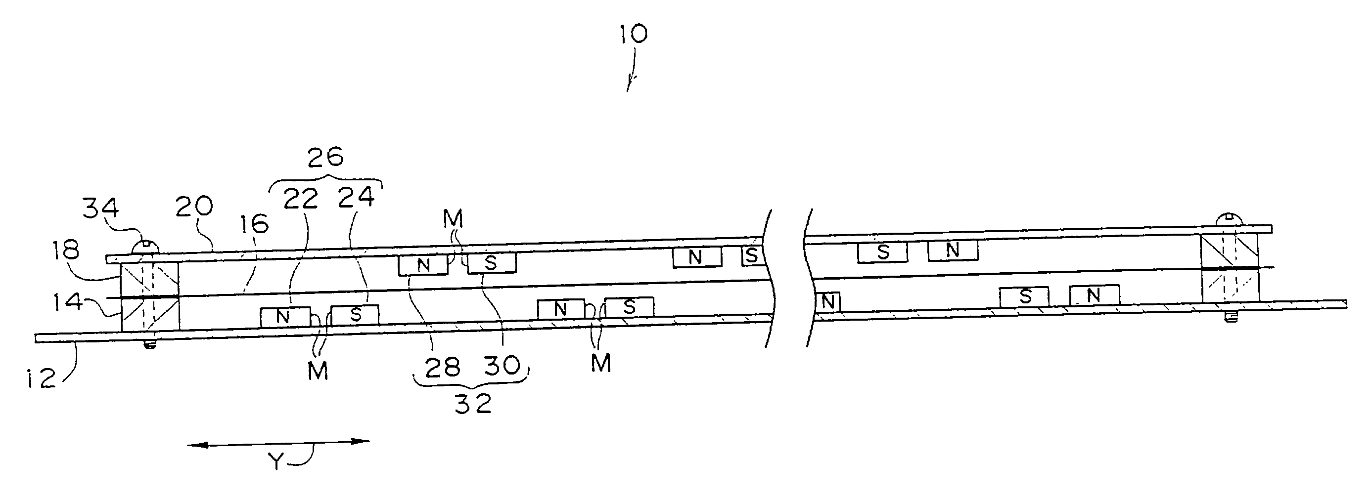
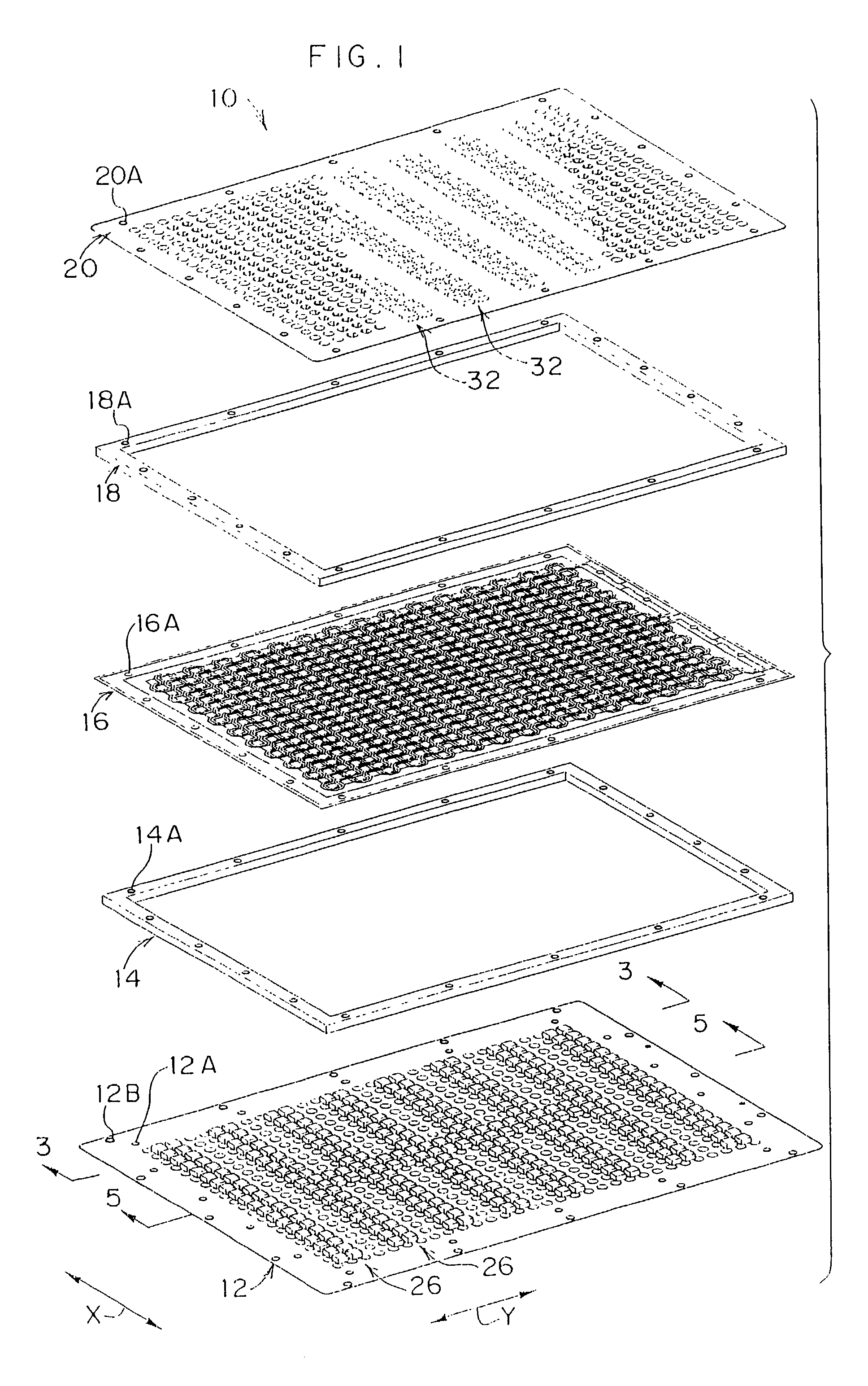
[0064] As shown in FIG. 1, a flat speaker 10 of the present embodiment is provided with a first yoke 12, a spacer 14, a diaphragm 16, a spacer 18, and a second yoke 20, which are arranged in this order.

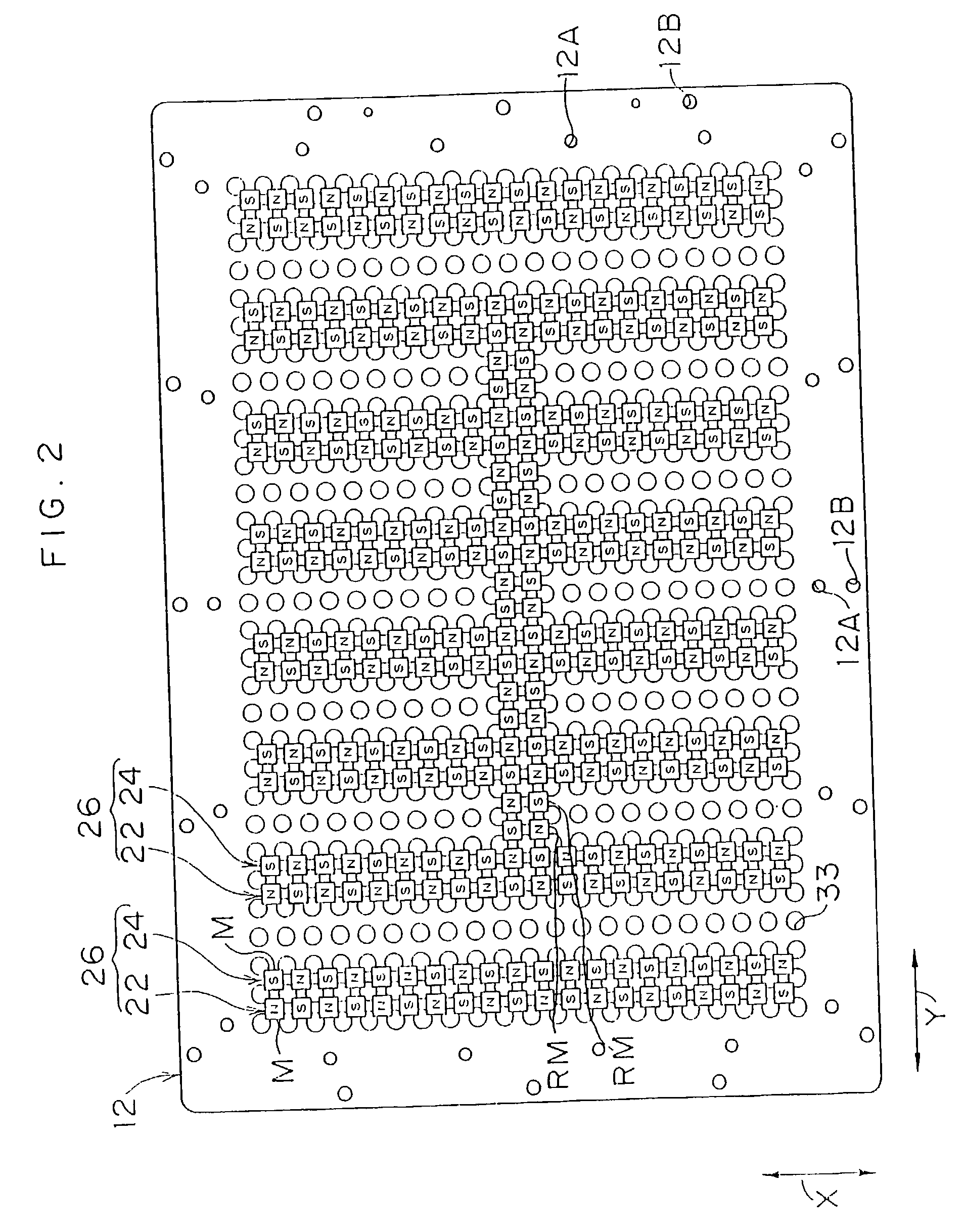
[0065] As shown in FIG. 2, the first yoke 12 is formed with magnetic bodies, and is formed in a flat board shape which is rectangular with a long side in the Y direction of the drawing.

[0066] As shown in FIGS. 2 and 3, first magnet groups 26 are provided in a plurality of rows (eight rows in the present embodiment), which are separated by a certain interval in the Y direction, at a diaphragm side surface of the first yoke 12. The first magnet groups 26 are formed of two rows of magnets, a first magnet row 22 and a second magnet row 24. At each row, quadrilateral permanent magnets M whose south poles face a diaph...

second embodiment

[0115] Second Embodiment

[0116] Next, a flat speaker 50 relating to a second embodiment of the present invention will be described.

[0117] As shown in FIGS. 11 and 12, the flat speaker 50 is provided with a yoke 52, which includes a plate-like member formed with magnetic bodies.

[0118] Twelve permanent magnets M are fixedly arranged at a magnet fixed portion 52A of the yoke 52 by glueing. The permanent magnets M are formed with substantially flat, quadrilateral shapes. The permanent magnets M are magnetized such that magnet faces with different polarities are mutually adjacently positioned, and are provided at predetermined spacings.

[0119] A diaphragm 54 is disposed near the magnet faces of the permanent magnets M at an upper face side of the yoke 52. The diaphragm 54 is substantially parallel with the magnet faces, and therefore with an upper face of the yoke 52.

[0120] An outer peripheral vicinity of a substantially rectangular frame body 58 is fixed at a diaphragm attachment portion ...

third embodiment

[0136] Third Embodiment

[0137] Next, a flat speaker 80 relating to a third embodiment of the present invention will be explained. The flat speaker 80 of the present embodiment is a variant example of the flat speaker 50 of the second embodiment.

[0138] As shown in FIG. 14, eight permanent magnets M are fixedly arranged at a magnet fixed portion 82A of a yoke 82. The permanent magnets M are magnetized such that magnet faces with different polarities are mutually adjacently positioned, and are provided at predetermined spacings.

[0139] A diaphragm 84 is disposed near the magnet faces at an upper face side of the yoke 82.

[0140] An outer peripheral vicinity of a substantially rectangular frame body 88 is fixed at a diaphragm attachment portion 82B of the yoke 82, with an unillustrated spacer interposed therebetween.

[0141] An edge 90 is formed continuously along an outer periphery at the frame body 88. The edge 90 is a resilient portion with a substantially semi-circular arc-shaped cross-se...


PUM


Abstract

A first conductor and a second conductor are provided at a diaphragm. The first and second conductors intersect magnetic force lines between north poles and south poles of permanent magnets M which are adjacent to one another. When electricity passes through the conductors, a direction in which a force from the magnetic field acts on the current is substantially orthogonal to a surface of the diaphragm. Therefore, the diaphragm can be oscillated in the direction orthogonal to the diaphragm surface. The conductors have widths of from 1000 mum to 2000 mum. Therefore, relative errors in the widths caused by etching can be greatly reduced compared to the prior art, and etching is easier. Moreover, the conductors are arranged in a zigzag pattern. Because the conductors do not have a coil form, a large number of through-holes is not required as in conventional products.

Description

[0001] 1. Field of the Invention[0002] The present invention relates to a diaphragm for a flat-type acoustic transducer, which is to be used in a flat-type acoustic transducer such as a flat-type speaker, a flat-type microphone, a flat-type speaker that is usable as a microphone, or the like, and relates to a flat-type acoustic transducer that uses this diaphragm for a flat-type acoustic transducer.[0003] 2. Description of the Related Art[0004] Examples of flat-type acoustic transducers include a dynamic flat-type speaker disclosed in Japanese Patent No. 3,159,714.[0005] In this flat-type speaker, a plurality of permanent magnets are disposed neighboring each other and separated by a predetermined spacing such that polarities thereof intersectingly oppose one another. A diaphragm is provided facing the permanent magnets and disposed at a predetermined separation therefrom.[0006] Coils are formed at the diaphragm in correspondence to the respective permanent magnets. The coils are fo...

Claims


Application Information

Patent Timeline
Patent Type & Authority Applications(United States)
IPC IPC(8): H04R9/00H04R7/04
CPCH04R7/04
Inventor SOTME, HIROMIMIYAZAKI, TOSHIIKU
Owner FPS
Why Eureka
Try Eureka