
Method and apparatus for varying the density of drilling fluids in deep water oil drilling applications

a technology for drilling fluids and deep water oil, applied in drilling pipes, drilling well accessories, sealing/packing, etc., can solve the problems of reducing the density of drilling fluids, affecting the drilling effect, and complicating the drilling process,

Inactive Publication Date: 2003-04-17
DUAL GRADIENT SYST
View PDF10 Cites 47 Cited by
  • Summary
  • Abstract
  • Description
  • Claims
  • Application Information

AI Technical Summary

Problems solved by technology

This is further complicated when drilling in deep water or ultra deep water because of the pressure on the sea floor by the water above it.
Otherwise, the pressure in the hole will force material back into the well bore and cause what is commonly known as a "blowout."
When the mud density is insufficient, the gases or fluids in the borehole can cause the mud to decrease in density and become so light that a blowout occurs.
Blowouts are a threat to drilling operations and a significant risk to both drilling personnel and the environment.
However, the primary method for minimizing a risk of a blowout condition is the proper balancing ofthe drilling mud density to maintain the well in a balanced condition at all times. While BOP's can contain a blowout and minimize the damage to personnel and the environment, the well is usually lost once a blowout occurs, even if contained.
While this is desirable, it unfortunately slows down the drilling process.
In some cases underbalanced drilling has been attempted in order to increase the drilling rate.
This system is expensive to install, as it requires separate lines, expensive to maintain, and very expensive to run.
While it has been proven desirable to reduce drilling mud density at a location near and below the seabed in a well bore, there are no prior art techniques that effectively accomplish this objective.

Method used


Image

  • Method and apparatus for varying the density of drilling fluids in deep water oil drilling applications
  • Method and apparatus for varying the density of drilling fluids in deep water oil drilling applications
  • Method and apparatus for varying the density of drilling fluids in deep water oil drilling applications

Examples


Embodiment Construction

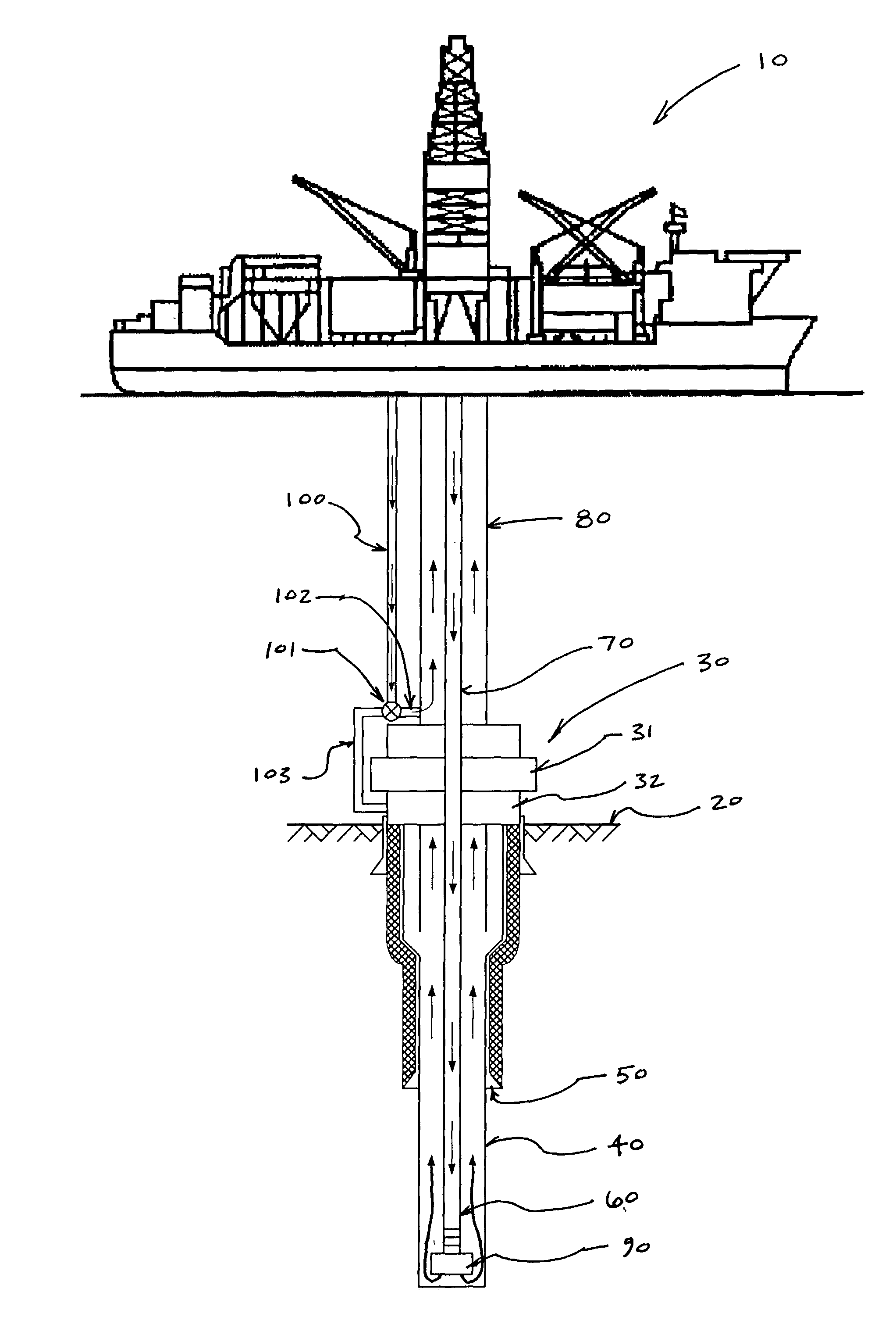
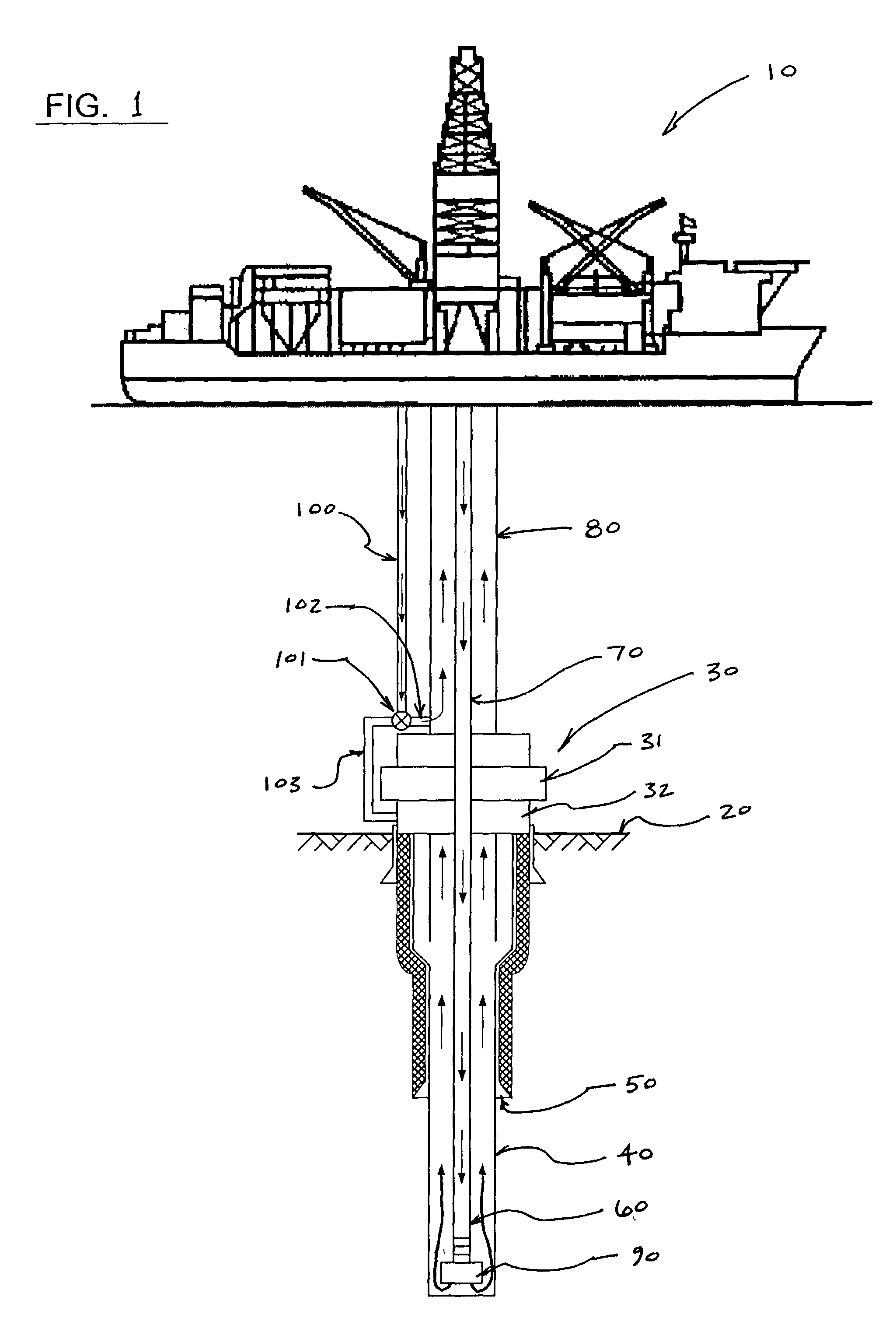
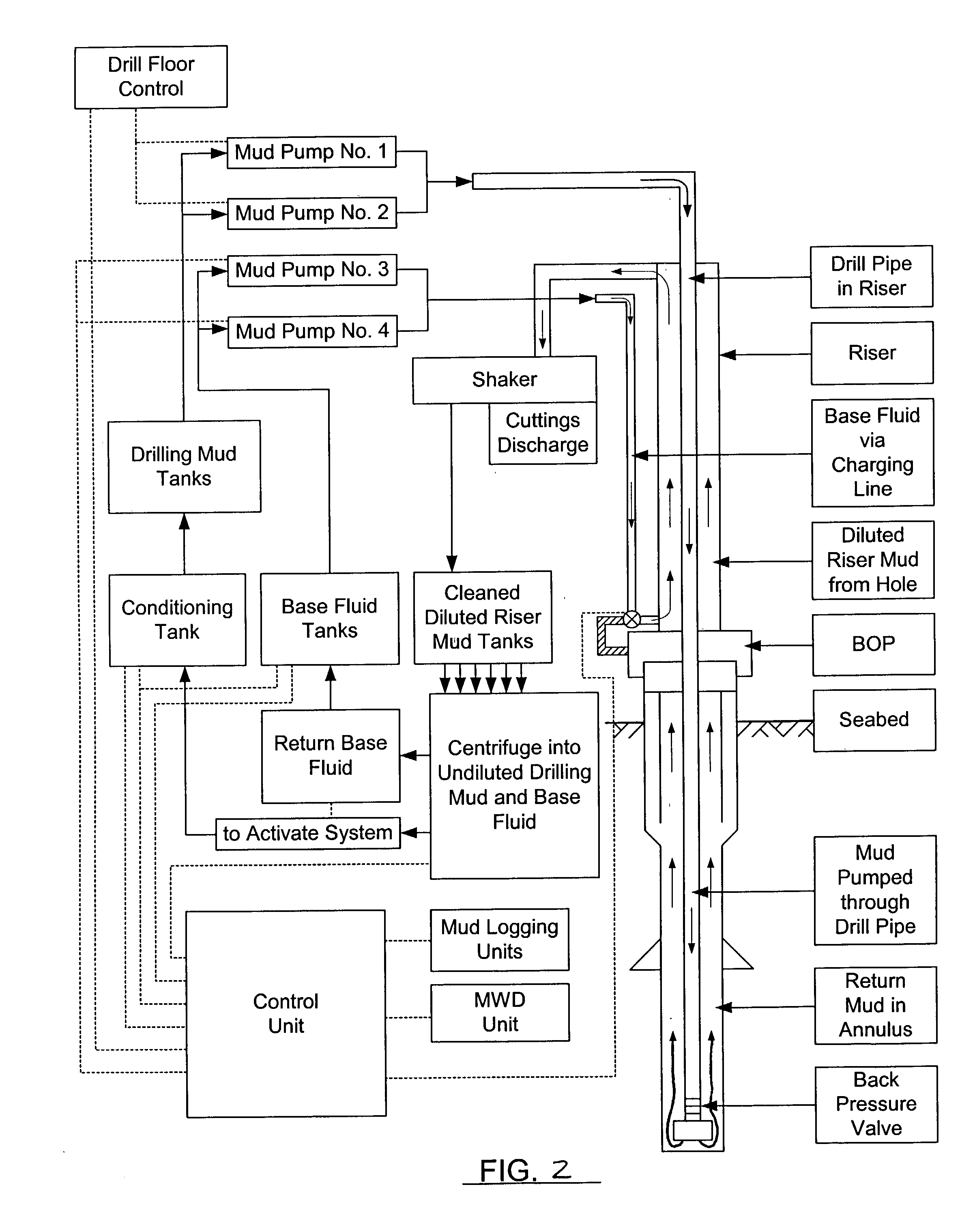
[0045] With respect to FIGS. 1-4, a mud recirculation system for use in offshore drilling operations to pump drilling mud: (1) downward through a drill string to operate a drill bit thereby producing drill cuttings, (2) outward into the annular space between the drill string and the formation of the well bore where the mud mixes with the cuttings, and (3) upward from the well bore to the surface via a riser in accordance with the present invention is shown. A platform 10 is provided from which drilling operations are performed. The platform 10 may be an anchored floating platform or a drill ship or a semi-submersible drilling unit. A series of concentric strings runs from the platform 10 to the sea floor or seabed 20 and into a stack 30. The stack 30 is positioned above a well bore 40 and includes a series of control components, generally including one or more blowout preventers or BOP's 31. The concentric strings include casing 50, tubing 60, a drill string 70, and a riser 80. A dr...


PUM


Abstract

A method and apparatus for controlling drilling mud density at a location either at the seabed (or just above the seabed) or alternatively below the seabed of wells in deep water and ultra deep water applications are disclosed. The present invention combines a base fluid of lesser density than the mud required at the wellhead to produce a diluted mud in the riser. By combining the appropriate quantities of drilling mud with base fluid, a riser mud density at or near the density of seawater may be achieved. The present invention also includes a wellhead injection device for attachment to the wellhead and for injecting the base fluid into the rising drilling mud at a location below the seabed. The riser charging lines are used to carry the low density base fluid to the injection device for injection into the drilling mud below the seabed. The cuttings are brought to the surface with the diluted mud and separated in the usual manner. The diluted mud is then passed through a centrifuge system to separate the heavier drilling mud from the lighter base fluid.

Description

[0001] The present application is a continuation-in-part of U.S. patent application Ser. No. 09 / 784,367 filed on Feb. 15, 2001.[0002] 1. Field of the Invention[0003] The subject invention is generally related to systems for delivering drilling fluid (or "drilling mud") for oil and gas drilling applications and is specifically directed to a method and apparatus for varying the density of drilling mud in deep water oil and gas drilling applications.[0004] 2. Description of the Prior Art[0005] It is well known to use drilling mud to drive drill bits, to maintain hydrostatic pressure, and to carry away particulate matter when drilling for oil and gas in subterranean wells. Basically, the drilling mud is pumped down the drill pipe and provides the fluid driving force to operate the drill bit, and then it flows back up from the bit along the periphery of the drill pipe and inside the open hole and casing for removing the particles loosed by the drill bit. At the surface, the return mud is...

Claims


Application Information

Patent Timeline
IPC IPC(8): E21BE21B1/00E21B7/128E21B21/00E21B21/06E21B21/08E21B21/10E21B21/14E21B33/035E21B33/076
CPCE21B21/001E21B21/063E21B2021/006E21B33/076E21B21/08E21B21/085
Inventor BOER, LUC DE
Owner DUAL GRADIENT SYST
Learn More