Recording method, recording medium, and recording system

Inactive Publication Date: 2003-04-17
HITACHI LTD
View PDF24 Cites 138 Cited by
  • Summary
  • Abstract
  • Description
  • Claims
  • Application Information

AI Technical Summary

Benefits of technology

[0030] FIG. 1 shows a diagram of the concept of the present invention, illustrating its object and advantageous effects;
[0031] FIG. 2 shows a block diagram of an optical recording and playback apparatus;
[0032] FIG. 3 shows a block diagram of another optical recording and playback apparatus;
[0033] FIG. 4 shows an example of the logical format of an information recording medium according to the present invention;
[0034] FIG. 5 shows a diagram of the concept of the present invention, illustrating its object and advantageous effects;
[0035] FIG. 6 shows a manner in which address information is allocated;

Problems solved by technology

Normally these processes come to an end without a hitch, but if the recording was unsuccessful for unexpected reasons, an error processing such as a retry or a replacement processing is performed.
Since a recording cannot be performed without the allocation information for the recording limited area, the recording medium cannot be recorded at this stage.
Therefore, to make a recording impossible, all the four pieces of address information are rendered incapable of correctly being played back.
In the event that the recording was not normally performed, an error processing is performed.
In the event that the recording was not performed normally, an error processing is performed.
In this case, since the target information and the allocation information for the limited area are recorded at the same location, an erasure of the target information results in an erasure of at least a part of the allocation information for the limited area, thereby making the playback of the information recorded on the recording medium impossible.

Method used


Image

  • Recording method, recording medium, and recording system
  • Recording method, recording medium, and recording system
  • Recording method, recording medium, and recording system

Examples


embodiment 1

[0046] (Embodiment 1)

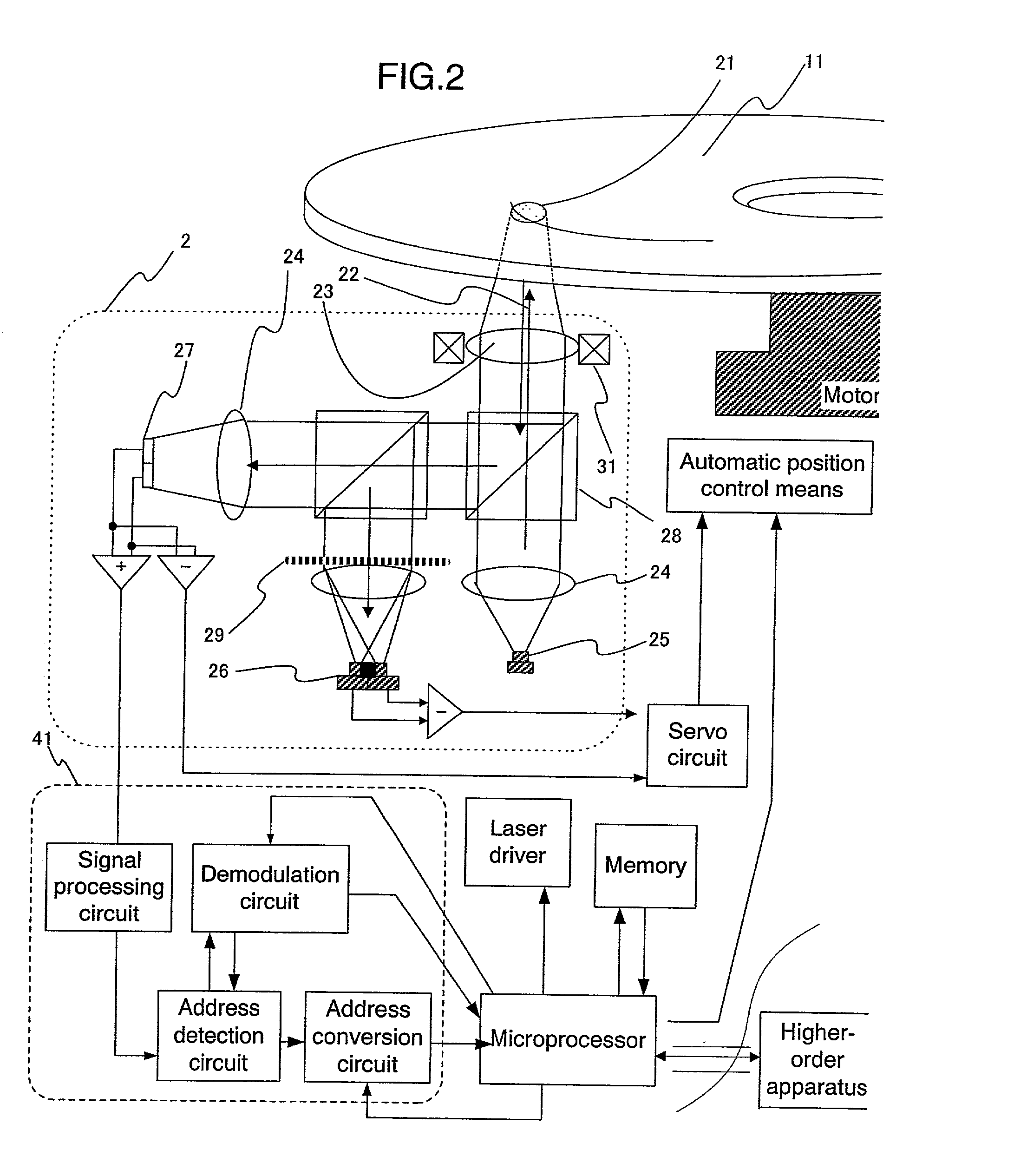
[0047] FIG. 3 shows an exemplary block diagram of a DVD-RAM recording and playback apparatus as an optical information recording apparatus. Hereafter, the operation of the apparatus on which a medium having no recording limit is mounted will be described.

[0048] A head 2 comprises a laser light source 25 (with a wavelength of about 660 nm in the case of a DVD-RAM) which emits light. The light is collimated into substantially parallel beams of light 22 through a collimator lens 24. The light beams 22 are irradiated onto an optical disc 11 via an objective lens 23, forming a spot 21. Thereafter, the light beams are guided to a servo detector 26 and a signal detector 27 via a beam splitter 28 and a hologram element 29, for example. Signals from the individual detectors are processed by addition or subtraction to provide servo signals such as a tracking error signal and a focus error signal, which are input to a servo circuit. Based on the tracking error and focus er...

embodiment 2

[0071] (Embodiment 2)

[0072] An example of the method for forming the recording-limited area will be described. In the DVD-RAMs, a physical ID (address information) is allocated at the head of each recording sector in the form of an embossed pit, as shown in FIG. 6. To ensure reliability, the address information for identifying a single sector is recorded quadruply.

[0073] The recording and playback apparatus in this embodiment determines that the address is correct if even at least one of the quadruple address information can be normally played back. Accordingly, in order to make a recording impossible, all the four pieces of address information are rendered incapable of being played back normally. As a method of rendering the normal playback of the address impossible, the ID error detection code (IED) which is added to each address information was made inconsistent with a corresponding ID. Specifically, one was added to the originally consistent IED. Such a method of rendering the I...

embodiment 3

[0075] (Embodiment 3)

[0076] In the present embodiment, the recording-limited area is allocated over the entire user area in a distributed manner, and the information concerning its locations and the target information were recorded on the disc as disc manufacturer information in the form of encrypted data. The present embodiment employs a specialized device driver. The specialized device driver has functions for, e.g., reading the encrypted data from the medium and registering it as an invisible file such that the recording-limited area does not enter the user area, and recording or playing back the disc by performing an address conversion. When the recording-limited area exists in different locations of the user area, as in the present embodiment, the disc cannot be played back by the conventional device driver, and a specialized software is required. This fact can be taken advantage of in constructing an applied system as according to Embodiment 5, which will be described later.

[0...


PUM


Abstract

An information recording medium and an optical recording system allow target information (such as an ad) to be displayed without requiring changes in hardware or physical specifications. The recording medium comprises a recording-limited area in which recording is made possible by canceling the limit after an instruction is issued for displaying the target information.

Description

[0001] 1. Field of the Invention[0002] The present invention relates to an allocation of recorded data in an information recording medium, and more particularly to a system for recording by means of generally available recording and playback drives.[0003] 2. Description of the Related Art[0004] As an example of an information recording system according to the related art, an optical recording and playback system for an information recording medium having target information (such as an advertisement) will be described by referring to FIGS. 3 and 9.[0005] FIG. 3 shows a block diagram of the optical recording and playback apparatus according to the prior art. A laser light source 25 which forms a part of an optical head 2 emits light (with a wavelength of about 660 nm in the case of a DVD-RAM). The light passes through a collimator lens 24 by which the light is collimated into substantially parallel beams of light 22. The light beams 22 are irradiated onto an optical disc 11 via an obj...

Claims


Application Information

Patent Timeline
IPC IPC(8): G11B7/00G11B20/10G11B7/0037G11B7/007G11B20/00G11B20/12
CPCG11B20/00086
Inventor HIROTSUNE, AKEMIMIYAMOTO, HARUKAZUNISHI, YOSHIKO
Owner HITACHI LTD
Why Eureka
Try Eureka