Sleeve-like printing or transfer form and device for chamfering the longitudinal ends of a sleeve-like printing or transfer form

Inactive Publication Date: 2003-04-24
MANROLANAD AG
View PDF12 Cites 6 Cited by
  • Summary
  • Abstract
  • Description
  • Claims
  • Application Information

AI Technical Summary

Problems solved by technology

Nevertheless, as the sleeve is being pushed onto the printing cylinder body, it may occur that the thin film placed on the latter is scr

Method used


Image

  • Sleeve-like printing or transfer form and device for chamfering the longitudinal ends of a sleeve-like printing or transfer form
  • Sleeve-like printing or transfer form and device for chamfering the longitudinal ends of a sleeve-like printing or transfer form
  • Sleeve-like printing or transfer form and device for chamfering the longitudinal ends of a sleeve-like printing or transfer form

Examples


Embodiment Construction

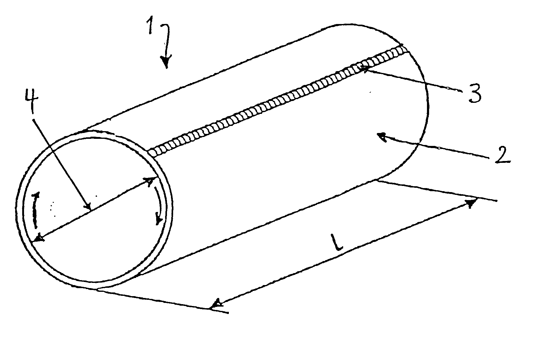
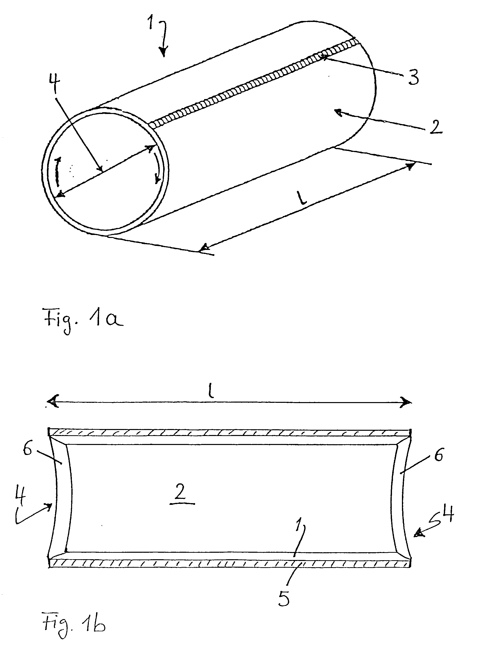
[0020] FIG. 1a shows in highly schematic form an exemplary embodiment of a support sleeve 1 made of a metallic material, which may be nickel, aluminum, steel, stainless steel or brass, for example. In the present case, the initial form was a rectangular, thin-walled piece of plate, which has been brought into the desired hollow cylindrical shape 2 of length 1 by bending. The edges of the piece of plate facing each other are preferably firmly connected to each other by means of a welded seam 3. The arrows indicate that, at one longitudinal end, which is provided at the first in the direction in which it is pushed onto the printing cylinder core, a chamfer 4 running all around is provided in the inner circumference.

[0021] FIG. 1b shows the chamfer 4 for a rubber sleeve in detail. The metallic support sleeve 1, preferably made of nickel, is provided on its outer circumference and its length 1 with a rubber coating 5. The chamfer 4 and therefore at the same time any possible deburring o...


PUM

PropertyMeasurementUnit
Diameteraaaaaaaaaa
Circumferenceaaaaaaaaaa
Sliding frictionaaaaaaaaaa

Abstract

A support sleeve made of a metallic material, preferably of nickel, is provided at at least one longitudinal end with a chamfer running all around in the inner circumference. This prevents damage to a film-like coating or thin intermediate sleeve, which surrounds the cylinder core to which the sleeve is fitted. A device for chamfering and deburring the longitudinal ends of the sleeve include a supporting body having a cylindrical journal with a diameter only slightly smaller than the internal diameter of the sleeve to be machined, in order to accommodate a longitudinal end of the sleeve and to guide the cut. A cutting holder is machined on the supporting body by means of which holder a cutter can be brought up to the inner circumference of the longitudinal end of the sleeve to be machined, and the supporting body can be rotated relative to the sleeve to be machined and pushed onto the journal.

Description

[0001] 1. Field of the Invention[0002] The invention relates to the field of conventional printing on a rotary printing machine (for example offset, gravure, flexo or screen printing) and more particularly to a sleeve-like form for a printing or transfer cylinder including a support sleeve having an inner circumference and a pair of longitudinal ends.[0003] The invention also relates to a device for chamfering the longitudinal ends of such a sleeve-like printing or transfer form.[0004] 2. Description of the Related Art[0005] In the current sleeve technique for channel-less printing--in particular with rubber blanket and printing form, but also other printing processes--it is usual, in order to fit the sleeve-like printing or transfer form to a printing cylinder, to push the printing or transfer form onto the printing cylinder as it is widened by means of compressed air. The removal of the compressed air has the effect of placing the printing or transfer form on the printing cylinder...

Claims


Application Information

Patent Timeline
IPC IPC(8): B23B5/16B41N1/20B41N3/00B41N7/00
CPCB23B5/168B41N1/20B41N3/00B41N2207/10B41P2227/20B41N2207/02B41N7/005
Inventor GRIESER, ALFONS
Owner MANROLANAD AG
Why Eureka
Try Eureka