Torch for thermal spraying

a technology of thermal spraying torch and discharge member, which is applied in the direction of spray nozzle, movable spraying apparatus, coating, etc., can solve the problems of limited gas supply to the outer periphery of the discharge member, easy corrosion of pipes, and almost no thermal spraying technology for carrying out surface treatment with respect to cylindrical inner surfaces

Inactive Publication Date: 2003-04-24
SHIMAZU KOGYO YUGENKAISHA
View PDF0 Cites 28 Cited by
  • Summary
  • Abstract
  • Description
  • Claims
  • Application Information

AI Technical Summary

Problems solved by technology

Pipes such as those for cooling medium used in boilers and power generators, pipes connecting chemical reaction equipment, pipes for delivering chemicals and carrying special materials are used under severe conditions; as a result, these pipes are easy to corrode.
Thus, there has been almost no thermal spraying technology for carrying out a surface treatment with respect to a cylindrical inner surface such as t...

Method used


Image

  • Torch for thermal spraying
  • Torch for thermal spraying
  • Torch for thermal spraying

Examples


Embodiment Construction

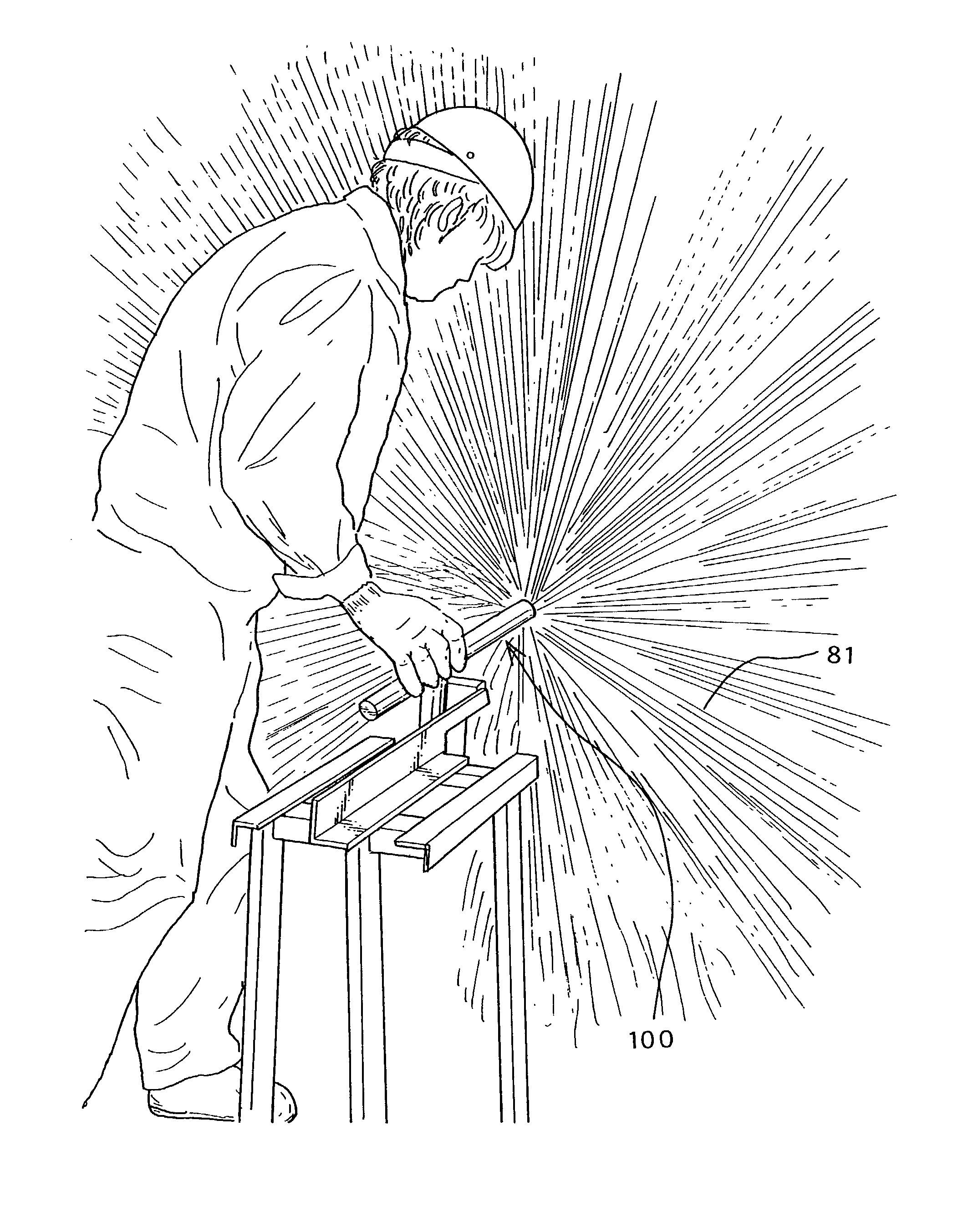
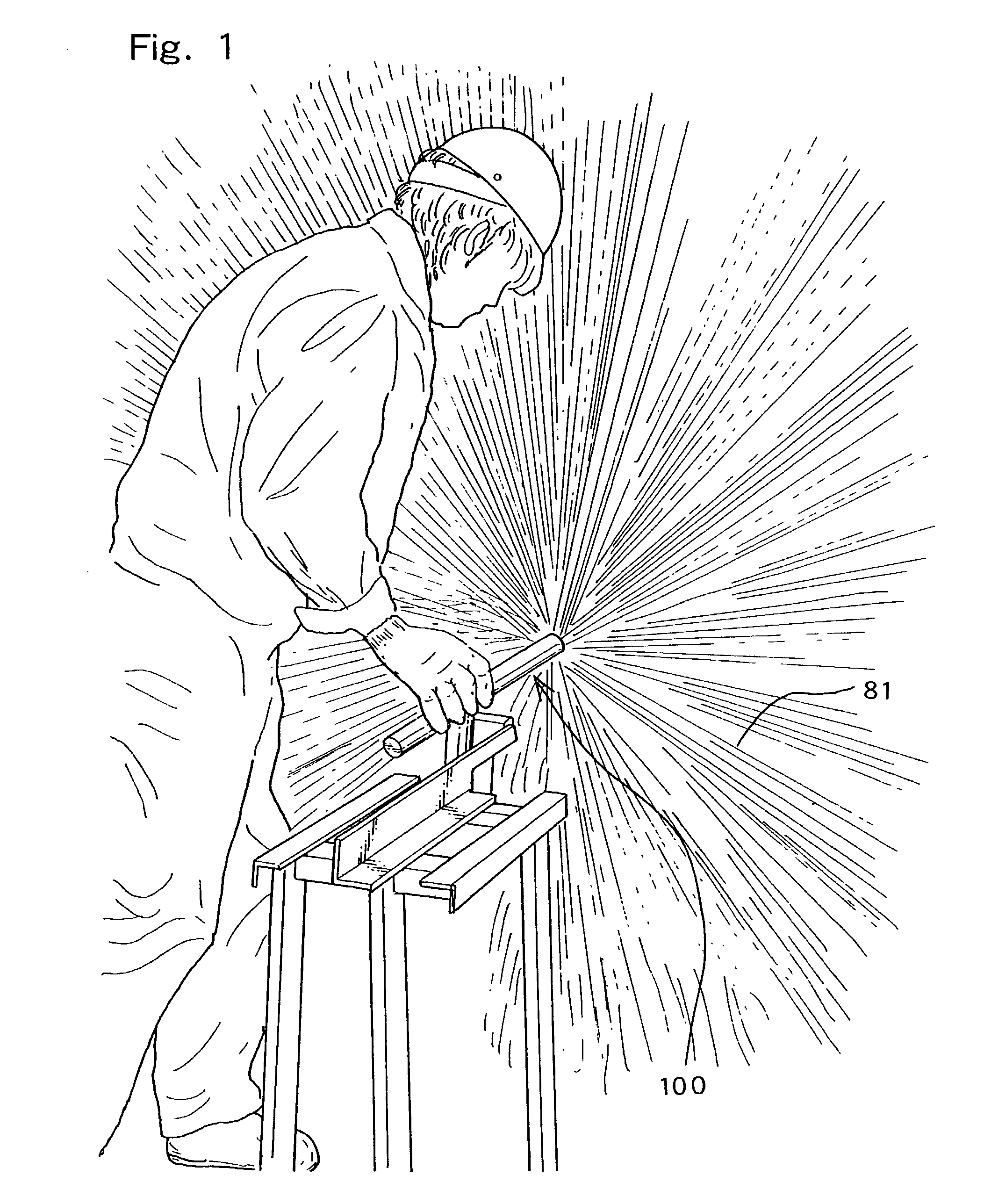
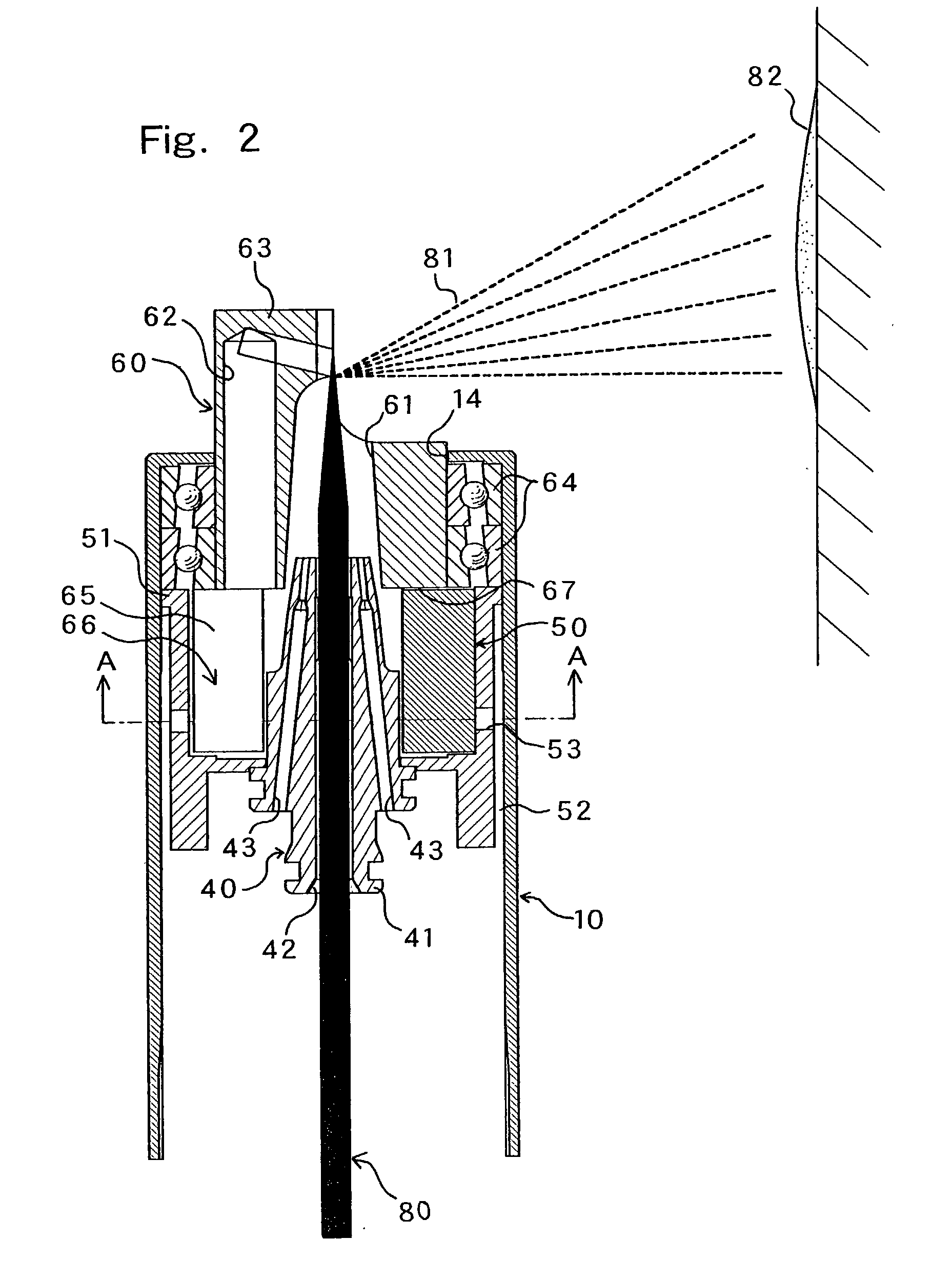
[0042] Best mode for carrying out the present invention will be described below with reference to the accompanying drawings. In FIG. 1 to FIG. 4, there is a thermal spraying torch 100 according to one embodiment of the present invention. The thermal spraying torch 100 of this embodiment is a so-called wire flame spraying type such that thermal spray material 80 formed as a wire rod is fused by heat obtained by burning a mixed gas of fuel gas and auxiliary gas such as oxygen, and thereby, droplets 81 are obtained. In this case, of course, metal powder may be used as the thermal spray material 80, and the thermal spray material 80 may be fused by plasma forming gas in an arc.

[0043] Further, the thermal spraying torch 100 of this embodiment substantially includes both inventions described in the first and second aspects; therefore, the thermal spraying torch 100 of this embodiment will mainly be described below.

[0044] As shown in FIG. 2 to FIG. 4, the thermal spraying torch 100 include...


PUM


Abstract

The thermal spraying torch 100 is capable of successively supplying a thermal spray material 80 heated and fused by a plasma forming gas in an arc generated between electrodes contained in an outer cylinder 10, or by a combustion gas supplied passing through the outer cylinder 10 and burned under high temperature conditions. The torch can spray the thermal spray material 80 via a nozzle 40 by the plasma forming gas or the combustion gas so that droplet(s) 81 can be formed, and a rotatable discharge member 60 is contained in a forward portion of the nozzle 40 and has a droplet passage 61 for the droplet(s) 81 at the center so that the droplet(s) 81 can be jetted together with the forming gas or the combustion gas. The discharge member 60 is formed with a projection 63, which changes a discharge direction of a droplet(s) 81 at the center of the distal end portion, and is formed integrally with a plurality of arm members 65, which project from the discharge member 60 and arranged in an air jet cylinder 50 that is contained in the outer cylinder 10 at the rear end, whereby an air jet space 66 for jetting a rotation air is formed, and rotational force is given to the discharge member 60 by air jetted from an air jet port 53 of the air jet cylinder 50 arranged outside the air jet space 66. Therefore, in the thermal spraying torch 100, the rotational speed of the discharge member 60 for radially discharging the droplet 81 can be set to a range from 800 to 6,000 rpm. Further, thermal spraying is carried out with respect to the inner surface of the pipes and the cylinder 91 so that the optimum sprayed coating film 82 can be formed. A process for thermal spraying with such a device is also disclosed.

Description

RELATED APPLICATIONS[0001] This application is the national phase of PCT application PCT / JP01 / 000589, filed Jan. 29, 2001, which designated the United States but was not published in English, the disclosure of which is incorporated herein by reference.FIELD OF THE INVENTION[0002] The present invention relates to a thermal spraying torch, which is used in the case of carrying out a surface treatment using a thermal spray material heated and fused by a plasma forming gas or combustion gas. In particular, the present invention relates to a thermal spraying torch, which is suitable for carrying out a surface treatment with respect to an inner surface of pipes, cylinders and the like.BACKGROUND ART[0003] Pipes such as those for cooling medium used in boilers and power generators, pipes connecting chemical reaction equipment, pipes for delivering chemicals and carrying special materials are used under severe conditions; as a result, these pipes are easy to corrode. For this reason, the in...

Claims


Application Information

Patent Timeline
IPC IPC(8): B05B7/08B05B7/20B05B13/06
CPCB05B7/0807B05B13/0636B05B7/201
Inventor SHIMAZU, TADAHIRO
Owner SHIMAZU KOGYO YUGENKAISHA
Why Eureka
Try Eureka