Computer based verification system for telecommunication devices and method of operating the same

a computer-based verification and telecommunications technology, applied in the field of computer-based verification systems for telecommunication devices and methods of operating the same, can solve the problems of designers facing a laborious process of finding out where the problem lies, the complexity of verification and the system is still the most time-consuming and critical

Inactive Publication Date: 2003-05-08
TRANSWITCH +1
View PDF0 Cites 13 Cited by
  • Summary
  • Abstract
  • Description
  • Claims
  • Application Information

AI Technical Summary

Problems solved by technology

A crucial component in these efforts, is the challenge to overcome the verification complexity.
Verification of telecommunications and computer based systems and components to be used in these systems is still a most time consuming and critical aspect of system design.
Generally, there are two major problems: a) to confirm that a specific design of a component conforms to the protocols, and b) a specific piece of equipment conforms to the protocols.
However, both solutions share a problem that any comprehensive test must include not only challenges with correct data but also ones with erroneous data, i.e. response behavior to both correct and erroneous stimuli must be checked.
When an error is found, the designer is faced with a laborious process of finding out where the problem lies.
Testbench creation is at least as complicated as the actual design of a component, most of the time more complicated.
The incorrect traffic is used to see if the design reacts and reports this incorrect traffic correctly.
Most testbenches are too project specific so that they cannot easily be reused in a new project.

Method used


Image

  • Computer based verification system for telecommunication devices and method of operating the same
  • Computer based verification system for telecommunication devices and method of operating the same
  • Computer based verification system for telecommunication devices and method of operating the same

Examples


Embodiment Construction

[0058] The present invention will be described with reference to certain embodiments and drawings but the present invention is not limited thereto but only by the attached claims. For example, the present invention will mainly be described with reference to the computer language C++ but other languages may be used, e.g. ADA.

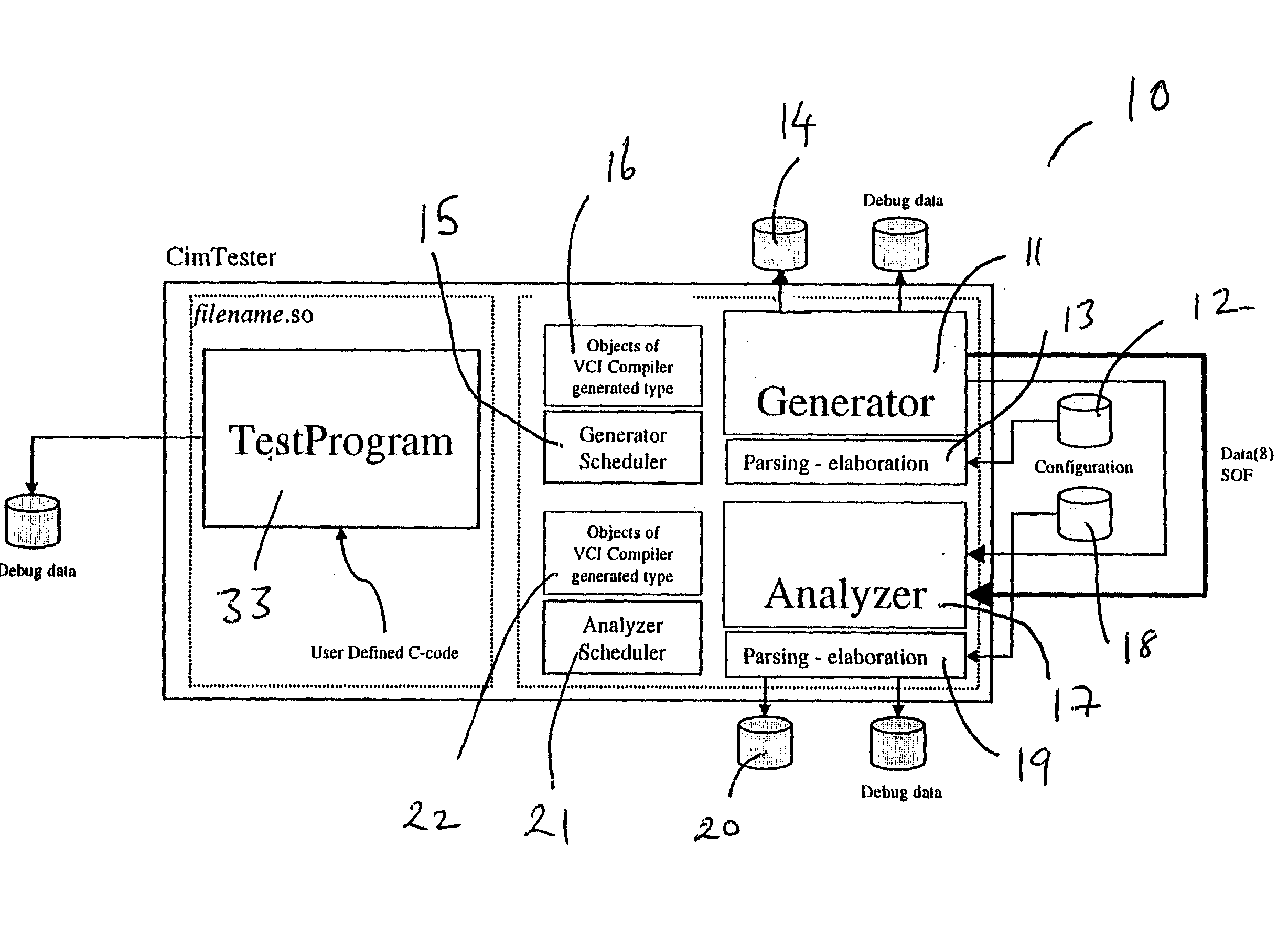
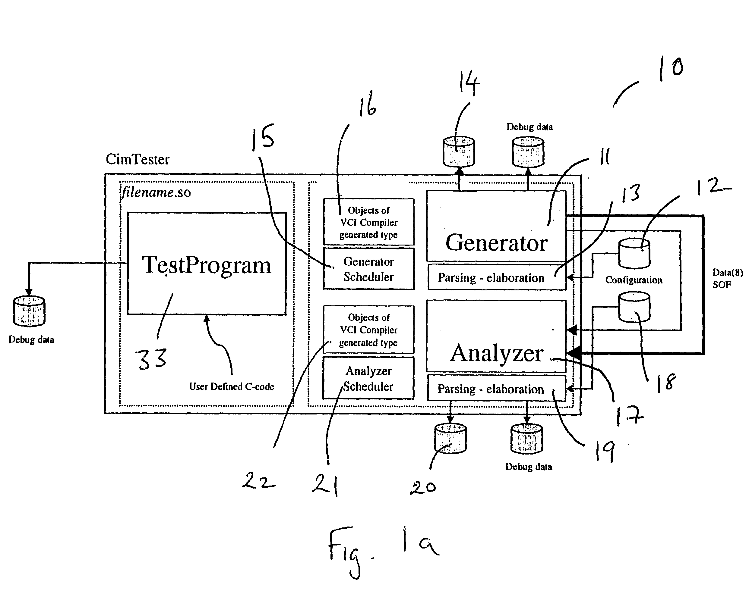
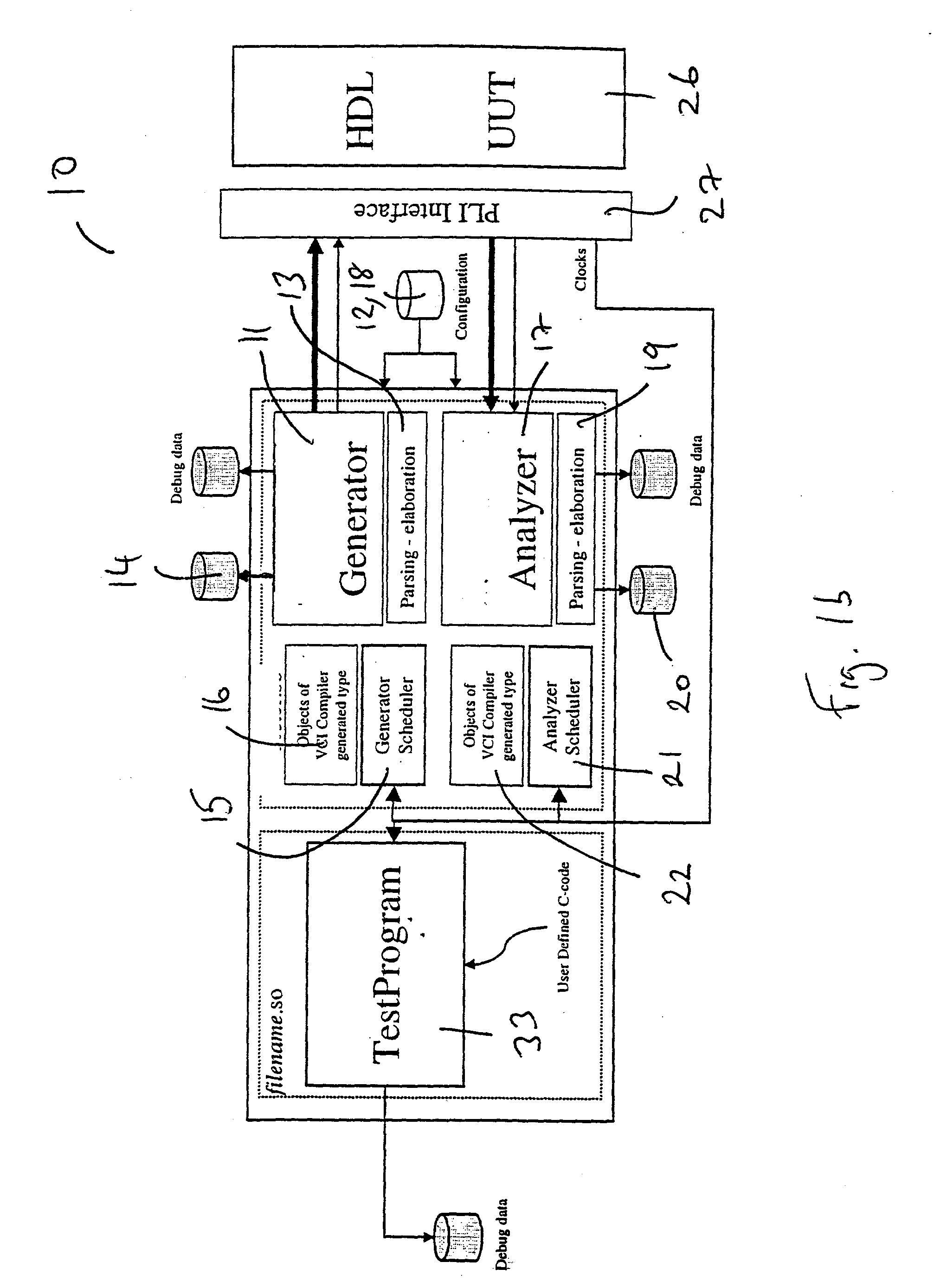
[0059] The present invention provides a computer-based design verification system, in particular a test bench system for generating and analyzing telecommunication data traffic, especially as related to a design of a telecommunications device or a component thereof. The verification or test bench system may be implemented in hardware but in a preferred embodiment the verification or test bench system is implemented in software, e.g. computer program products written in a suitable computer program language such as C++ and their execution on a computing device. The computer program product when run on a suitable computing device generates and analyzes telecommunica...


PUM


Abstract

A computer apparatus is described for displaying and manipulating sequences of frames of hierarchically organized framed data. The apparatus comprises means for generating a graphical user interface on a display screen, the graphical user interface having means for displaying a representation of a hierarchy of the framed data. The computer apparatus also has a pointing device for selecting a portion of the representation of the hierarchy to generate a control signal, and means responsive to the control signal to display a portion of the framed data corresponding to the selected portion of the representation of the hierarchy. The graphical user interface may be used in a computer based verification system for the analysis and display of a sequence of frames of framed data, comprising: means for generating a frame generator for receiving the frame sequence, the frame generator comprising means for processing the frame sequence in accordance with a protocol to form a modified frame sequence and for associating with each frame a description data structure for that frame, and means for outputting the modified frame sequence and the frame description data structure.

Description

[0001] The present invention relates to a verification system, in particularly a test bench system and method for verifying telecommunication system component and component design conformance with protocols and well as a usr graphics interface to be able to view traffic data manipulated by the verification / test bench system or method.TECHNICAL BACKGROUND[0002] Computer and telecommunications technology has created a huge potential for integration. The design community has tackled a variety of subjects that try to make the maximum use of this potential by mastering this increased complexity. A crucial component in these efforts, is the challenge to overcome the verification complexity. Verification of telecommunications and computer based systems and components to be used in these systems is still a most time consuming and critical aspect of system design. Generally, all such systems and components operate in accordance with a certain protocol. A protocol is a set of rules which rela...

Claims


Application Information

Patent Timeline
Patent Type & Authority Applications(United States)
IPC IPC(8): G06F17/50H04L12/26H04L29/06
CPCG06F17/5022H04L12/2697H04L69/03H04L43/50H04L29/06G06F30/33H04L9/40
Inventor VANDEWEERD, IVOCOENEN, STEVEN
Owner TRANSWITCH
Why Eureka
Try Eureka