X-ray detection

a technology of x-ray detection and x-ray beam, which is applied in the field of x-ray detection, can solve the problems of reducing the image quality of an imaged object, affecting the image quality of the imaged object, and the size and x-ray intensity distribution of the resulting beam may also vary in an undesired way

Inactive Publication Date: 2017-01-10
KONINKLJIJKE PHILIPS NV
View PDF7 Cites 6 Cited by
  • Summary
  • Abstract
  • Description
  • Claims
  • Application Information

AI Technical Summary

Benefits of technology

[0008]It has also been shown that, due to thermal expansion of the rotating anode as thermal energy caused by decelerating electrons dissipates into the anode, the focal spot's position on the rotating anode may drift away from its desired position. The size and X-ray intensity distribution of the resulting beam may also vary in an undesired way. It would be helpful to allow for correction of the effect of thermal anode heating.
[0067]It is further to be understood that the base plane is defined as the plane tangential to the frusto-conical (chamfered) surface of the rotating anode, upon which the focal spot is positioned. In other words, the base plane is in the same plane as a chamfer angle of the rotating anode onto which the electron beam is directed. As the area of the focal spot, and the area in which it may move is usually very small in comparison with the area of the frusto-conical section, a good approximation is that that the motion of the focal spot occurs around a centre position (vertex) on a flat plane. The effects of this approximation do not materially affect the operation of the present invention. The approximation does, however, serve to allow an easier visualization of the geometry.

Problems solved by technology

A spectral detection CT system can suffer from the unknown spectral variability of a rotating anode X-ray source caused by changes in the target material of the rotating anode.
This may create high frequency alterations of the X-ray spectrum, which could degrade the image quality of an imaged object.
The size and X-ray intensity distribution of the resulting beam may also vary in an undesired way.

Method used


Image

  • X-ray detection
  • X-ray detection
  • X-ray detection

Examples


Embodiment Construction

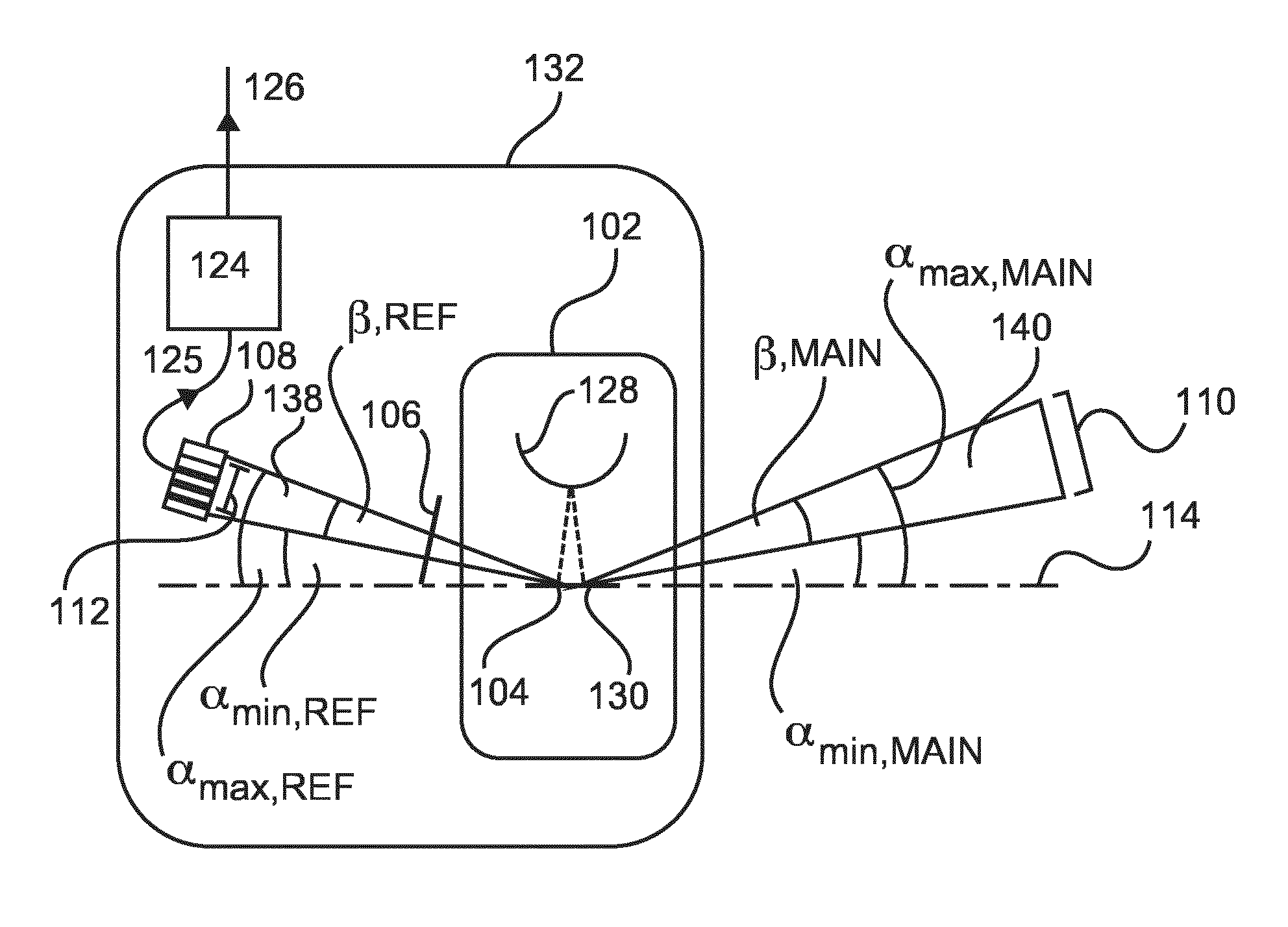
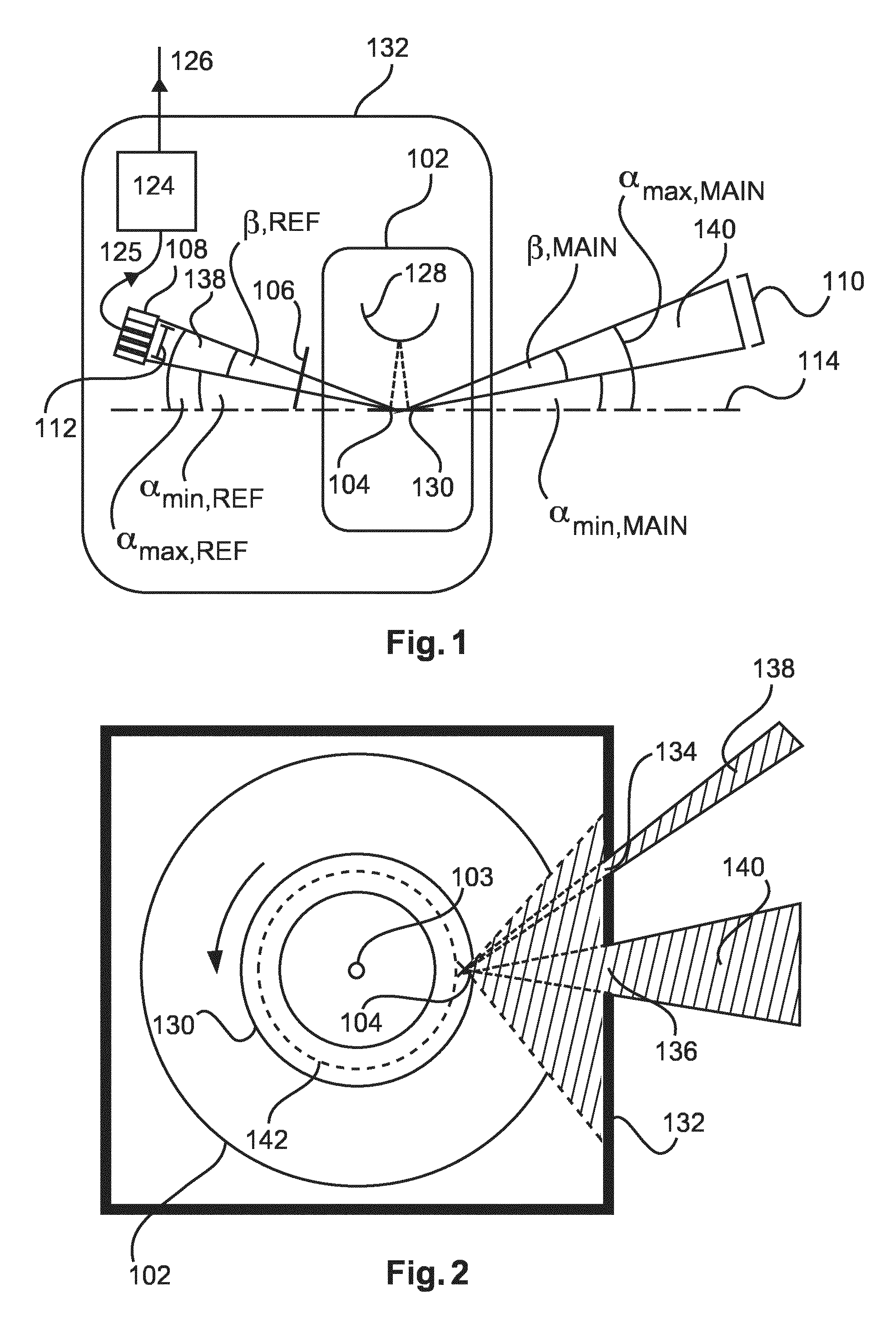
[0096]FIG. 1 schematically illustrates an X-ray tube housing assembly 132 according to the invention. The X-ray tube housing assembly 132 comprises an X-ray tube 102 contained inside the source. The X-ray tube has a sealed envelope maintaining a vacuum inside it. Inside the tube there is a cathode 128 arranged in proximity to a rotating anode 130.

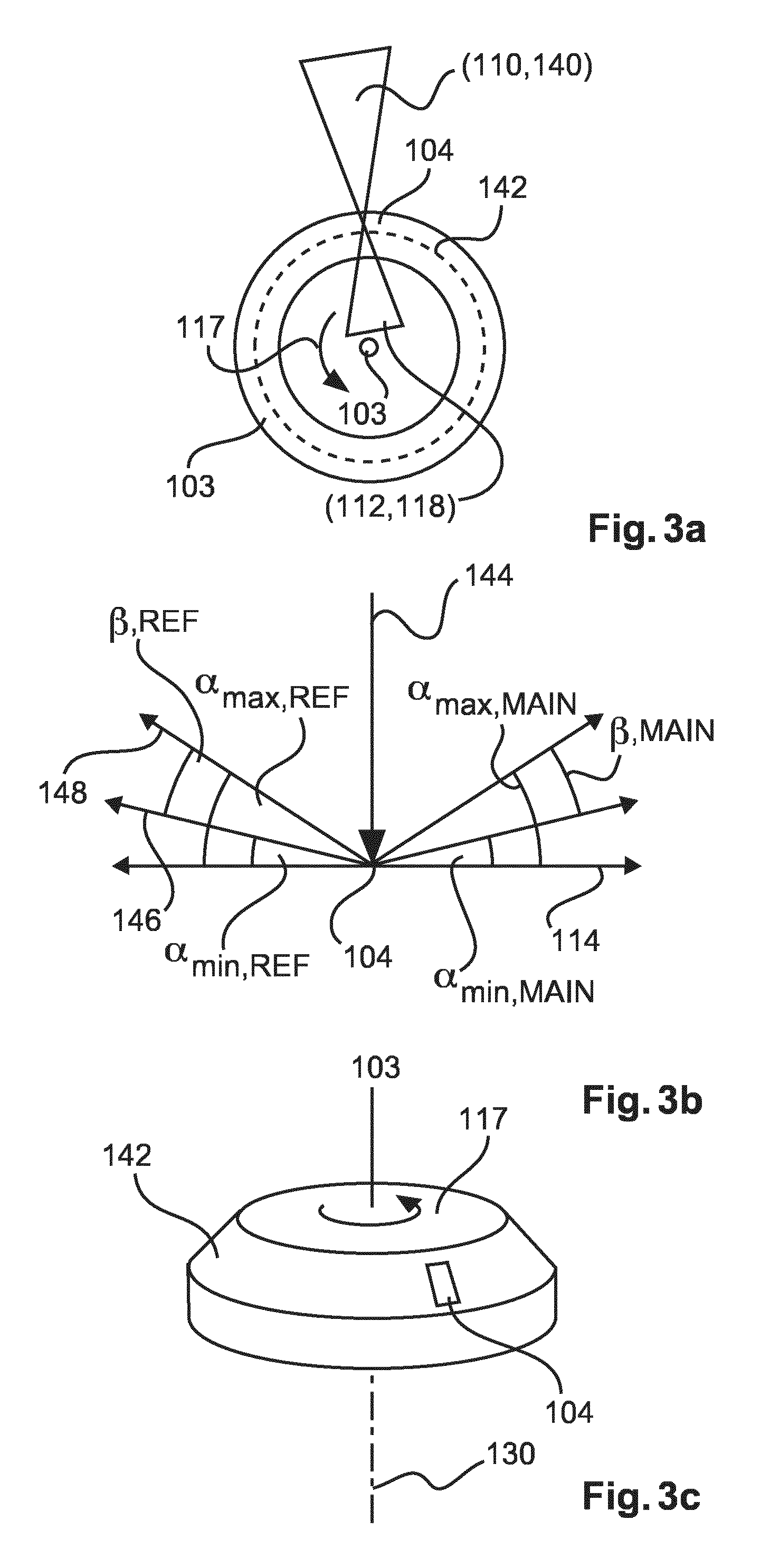
[0097]When an appropriate voltage is applied across the cathode and rotating anode, an electron beam travels through the vacuum and impinges on the rotating anode 130. The rotating anode, as used in a CT system, has a frusto-conical (segment of a cone) form, an example of which is shown in FIG. 3c. The point at which the X-ray beam impinges on the rotating anode 130 is known as the focal spot 104. The focal spot is located on the slanted side (chamfer) of the frusto-conical form. X-rays are emitted from the focal spot as a result of the rapid deceleration and acceleration of the electrons, leading to the emission of “Bremsstrahlung” radiati...


PUM


Abstract

Rotating anode X-ray tubes degrade over time because of the action of the electron beam altering the surface of the focal spot area of a rotating anode. This causes a degradation in a resulting object image, when the source is used in an imaging application. An X-ray tube housing assembly is discussed which allows the correction of such effects. In particular, an additional beam of the X-radiation, which is not used for imaging, may be used to correct such effects.

Description

CROSS-REFERENCE TO PRIOR APPLICATIONS[0001]This application is the U.S. National Phase application under 35 U.S.C. §371 of International Application No. PCT / EP2014 / 068141, filed on Aug. 27, 2014, which claims the benefit of European Patent Application No. 13183089.5, filed on Sep. 5, 2013. These applications are hereby incorporated by reference herein.FIELD OF THE INVENTION[0002]The present invention relates to X-ray detection.BACKGROUND OF THE INVENTION[0003]In rotating anode tube X-ray sources electrons are accelerated between a cathode and the rotating anode across a kilo-Volt potential difference so that they impact onto the focal track of the rotating anode. In the process, X-rays are generated, which are said to emanate from a “focal spot” at the point of electron beam impact on the rotating anode. Due to the energy dissipated in the impact, the rotating anode's surface may be modified in the process, and small pits and cracks may begin to appear.[0004]As a consequence, the X-...

Claims


Application Information

Patent Timeline
Patent Type & Authority Patents(United States)
IPC IPC(8): H01J35/00A61B6/00H05G1/46H01J35/10H01J35/18A61B6/04
CPCH01J35/18H05G1/46A61B6/585A61B6/4035A61B6/4266A61B6/586H01J35/00H01J35/10A61B6/0407A61B6/4441A61B6/4464A61B6/54A61B6/5258A61B6/032
Inventor BEHLING, ROLF KARL OTTO
Owner KONINKLJIJKE PHILIPS NV
Why Eureka
Try Eureka