Insulating packaging material and related packaging system

a packaging material and insulation technology, applied in the field of packaging systems, can solve the problems of thermal penetration gap around each "bubble", and achieve the effects of increasing the volume of trapped air, reducing the gap, and keeping hea

Inactive Publication Date: 2003-05-08
THERMAFREEZE PRODS CORP
View PDF6 Cites 35 Cited by
  • Summary
  • Abstract
  • Description
  • Claims
  • Application Information

AI Technical Summary

Benefits of technology

[0014] 2. When a producer laminates bubble wrap to foam or another substrate for thermal protection purposes using prior art approaches, it is easiest to manufacture the lamination with the flat side of the bubble wrap against the substrate. The downside of the finished product made in that manner is that there is a thermal penetration gap around each "bubble" where the lower edges of the bubble join the flat side of the bubble wrap structure. In such a configuration, heat from conduction finds an easy entry into the payload area of the pouch, liner, etc., by conveying heat energy from the surrounding area to the penetration gaps between the bubbles. The heat energy will transfer more slowly through the trapped air inside the bubbles but will move quickly through the penetration gaps to the interior of the pouch, liner, etc.
[0053] Although for very extreme, low ambient temperature conditions the heating of the intermediate layer of packet material may be desirable, in some conditions, merely hydrating the packet material is sufficient without any heating, with the unheated and initially unfrozen packet material serving as a "cold sink," absorbing the extreme cold from the ambient until it itself becomes frozen, thereby greatly assisting in the prevention of the extremely cold ambient reaching the usually refrigerated perishable in the innermost chamber of the packaged box.

Problems solved by technology

The downside of the finished product made in that manner is that there is a thermal penetration gap around each "bubble" where the lower edges of the bubble join the flat side of the bubble wrap structure.

Method used


Image

  • Insulating packaging material and related packaging system
  • Insulating packaging material and related packaging system
  • Insulating packaging material and related packaging system

Examples


Embodiment Construction

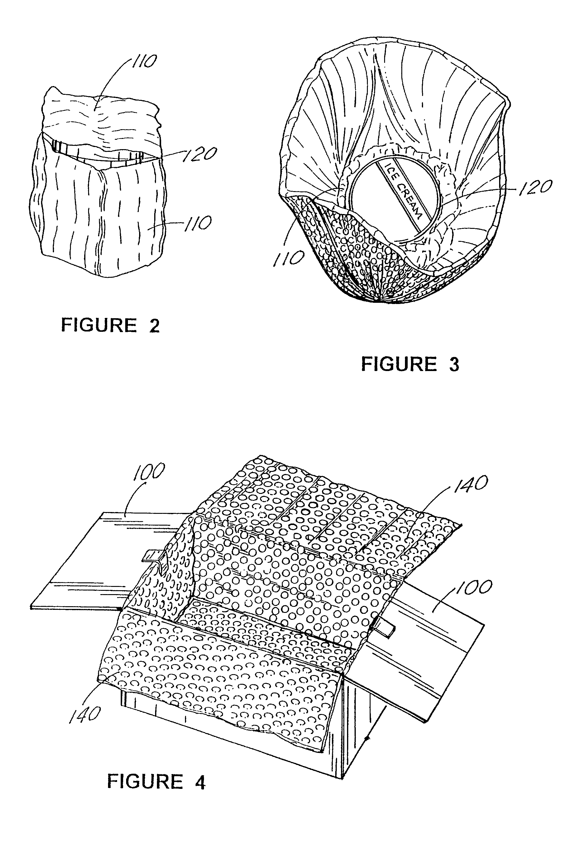
Preferred Protective Packing Approaches (FIGS. 2-9)

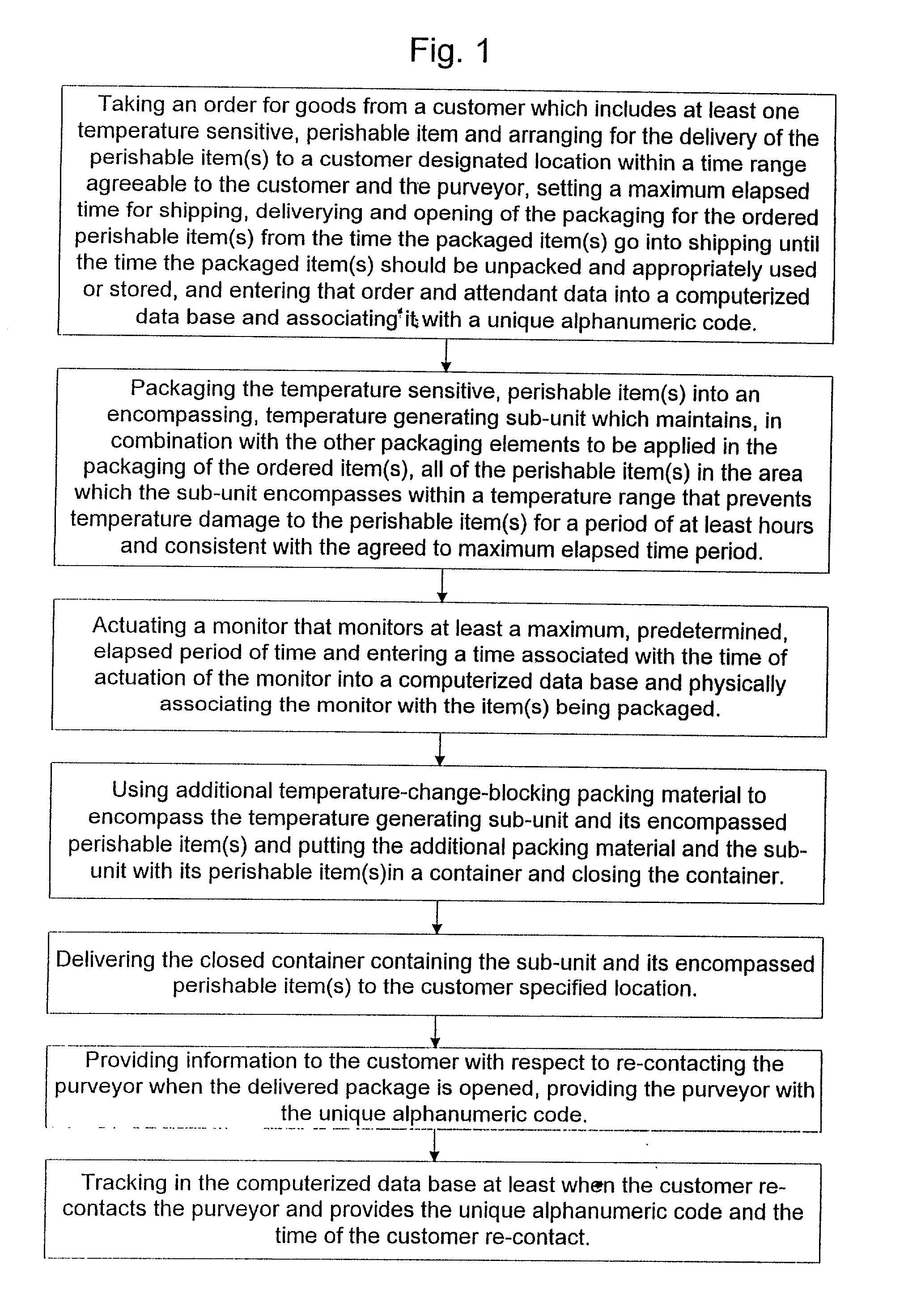
[0075] The preferred, exemplary embodiment of the present invention provides a "safe delivery.TM. system for perishable goods, including groceries, which keeps the cost as low as possible for the purveyor, allowing the purveyor to use some components, e.g., corrugated boxes that likely are already in inventory. Several other elements are involved to solve the total problem. Some are tangible products and some are tangible instruments used in combination with business methods; both used to plan and verify successful shipments. All of the system elements are listed below, with reference primarily to FIGS. 2-9:

[0076] 1. An appropriate container 100 (note FIGS. 4, 6, 7 & 8) for the perishable groceries, preferably rigid or at least self-supporting in its structure, and preferably a relatively inexpensive version of a corrugated cardboard box 100 (e.g., one with a single flute) or corrugated material, used to contain the perishable groce...


PUM

PropertyMeasurementUnit
WEIGHTaaaaaaaaaa
time period of timeaaaaaaaaaa
thickaaaaaaaaaa

Abstract

Insulating packaging material is wrapped or otherwise positioned around the typically temperature sensitive product, with the packing material including, alternatively, 1 ply (FIG. 22; metallized plastic film), 2 ply (FIGS. 23 & 24) and 3 ply (FIG. 25) material, in which some of the 2 ply & 3 ply embodiments include a layer of bubble wrap material having its bubble side placed or laminated against the flat side of the adjacent ply, which adjacent ply can be, for example, a mettalized plastic film or a foam layer or both layers can be included. With such a bubble side arrangement, multitudinous air pockets are formed between the bubbles of the bubble wrap and the other ply's typically flat interfacing surface. A separate layer of bubble wrap also preferably is placed about the interior of the box with its bubble side placed against the interior flat surfaces of the box, with the bubbles forming air pockets with the flat sides, further enhancing the insulating properties of the packaging for the goods. An exemplary system for delivering perishable groceries (120 / 120'), including a corrugated cardboard or other type box (100); a source of cold (or heat as needed) maintaining the temperature inside the box within a desired temperature range for hours or days, using an all encompassing pouch of packet material (110 / 10), used individually (FIGS. 2 & 3) or collectively (FIGS. 5 & 6), with each packet (17) containing a super-absorbent polymer (14, FIG. 12) which is hydrated (14', FIG. 12A) and then either frozen (e.g., in a freezer) or heated (e.g., in a microwave), without producing moisture as the polymer returns to its natural state; a protective cover (130) protecting the box and its contents from heat radiation (e.g., sunlight).

Description

REFERENCE TO RELATED APPLICATION & PATENTS[0001] This application is a continuation-in-part of Ser. No. 09 / 366,446 filed Aug. 3, 1999 entitled "Computerized, Monitored, Temperature Affected, Delivery System for Perishable Goods," being issued as Patent ## on ##Date. Reference also is hereby made to the patent application entitled "Hydration and Freezing Plant for Flexible Refrigerant Media" filed Jul. 11, 1997 as Ser. No. 08 / 893,405, one of the two co-inventors, namely, Messrs. Murray and Gaude, being the inventor hereof, namely, Mr. Murray, now abandoned in favor of the patent application entitled "Modular Hydration and Freezing Plant for Flexible Refrigerant Media" filed May 8, 1998 as Ser. No.09 / 075,429, also filed by Messrs. Murray and Gaude, being issued as U.S. Pat. No. 5,966,962 on Oct. 19, 1999, and co-pending application entitled "Porous, Laminated, Super Absorbent, Hydratable, Temperature Control Pack System" filed May 15, 1998 as Ser. No. 09 / 079,872 by Messrs. Murray & Ga...

Claims


Application Information

Patent Timeline
Patent Type & Authority Applications(United States)
IPC IPC(8): B65B25/00
CPCB65B25/001Y10T428/24661Y10T428/1334
Inventor MURRAY, JOSEPH C.
Owner THERMAFREEZE PRODS CORP
Why Eureka
Try Eureka