Method when cleaning a filter

a filter and filter material technology, applied in the field of filter cleaning, can solve the problems of increased resistance and thus energy consumption, dust penetrates into the filter material, and the emission of dust through the element is noticeable, and the effect of increasing the energy consumption

Inactive Publication Date: 2003-05-15
GENERAL ELECTRIC TECH GMBH
View PDF16 Cites 20 Cited by
  • Summary
  • Abstract
  • Description
  • Claims
  • Application Information

AI Technical Summary

Benefits of technology

[0010] A second object is to devise a method for determining the frequency and intensity for cleaning barrier filters, providing an increased life for the filter elements relatively to known strategies of cleaning.
[0012] The present invention refers to a method for cleaning a barrier filter, comprising a plurality of filter elements, of woven fabric or felt, arranged to separate particles out of a polluted gas. The filter elements are cleaned, separately or in groups, by pressurized air pulses, the frequency, the maximum pressure, and the duration of which can be varied by an adjustment in order to minimise the total emission of dust and maximise the life of the filter elements.

Problems solved by technology

However, in practice some dust penetrates into the filter material, usually a felt, and a small share thereof passes through.
This improves the separation, but as a negative consequence it provides an increased resistance and thus an increased energy consumption.
At the second decceleration, forces of inertia lead to the fact that remaining dust penetrates deeper into the filter material and the amount which thereby passes through the element provides a noticeable short-time emission increase.

Method used


Image

  • Method when cleaning a filter
  • Method when cleaning a filter

Examples


Embodiment Construction

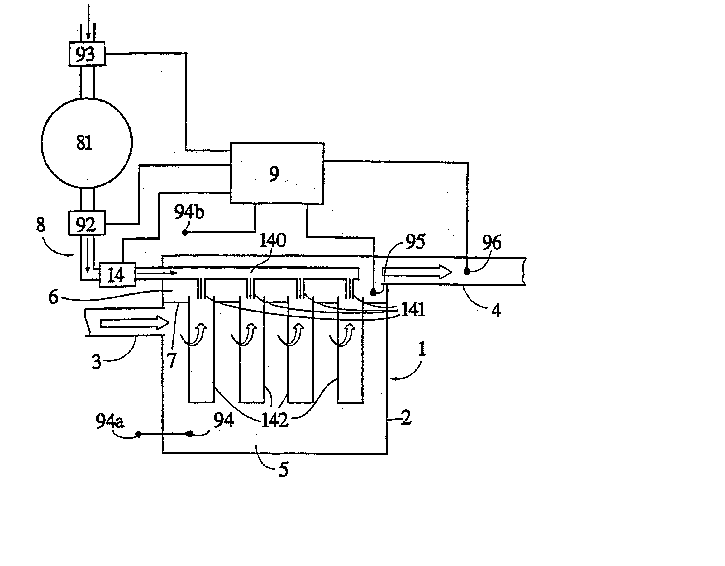
[0027] In FIG. 1 and FIG. 2, a tubular filter 1 with a housing 2, an inlet 3 for the gas to be purified, and an outlet 4 for the purified gas are disclosed. The tubular filter 1 is divided into a raw gas chamber 5 for the incoming gas and a pure gas chamber 6 for the outgoing gas by an intermediate wall 7.

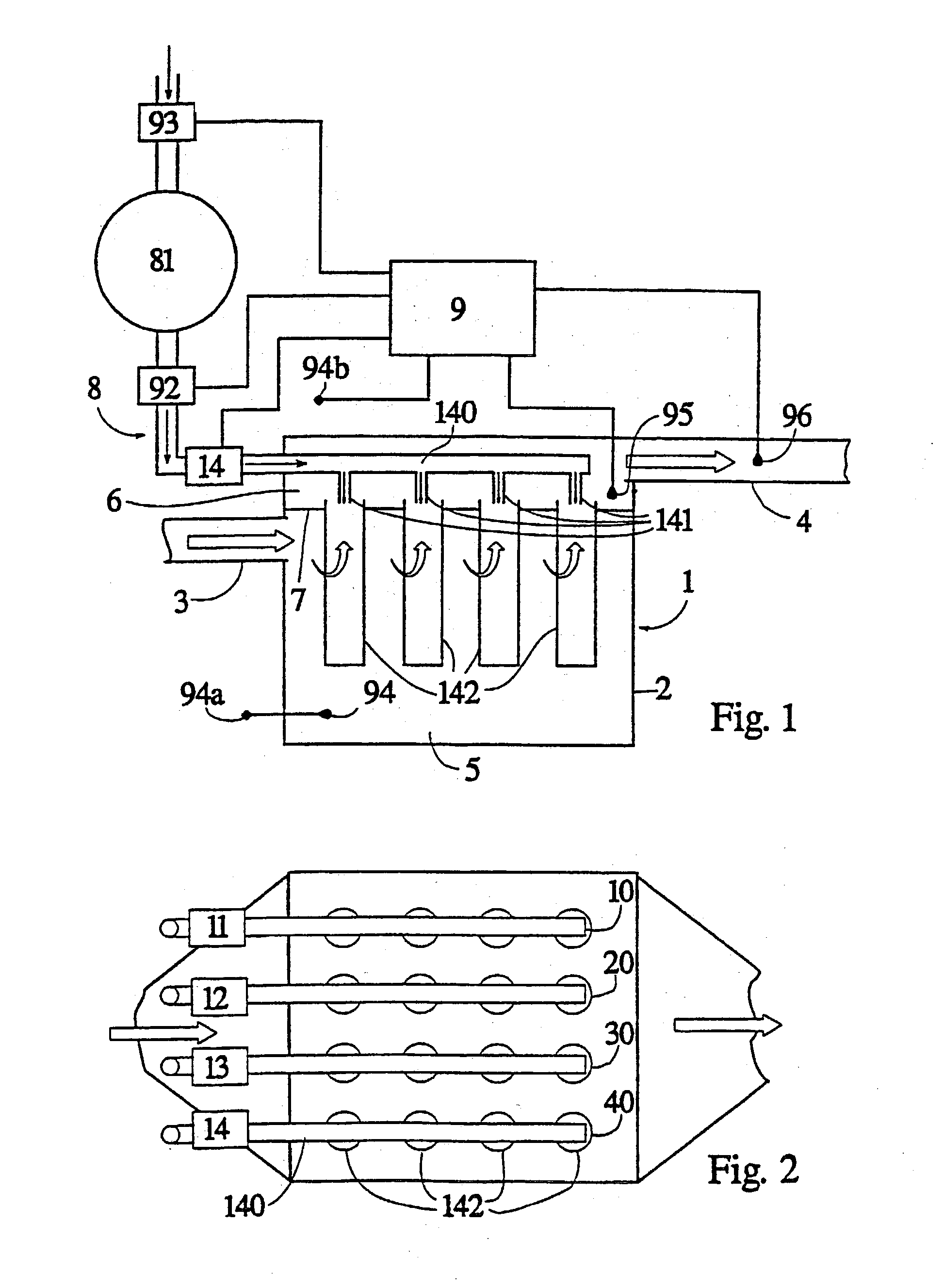
[0028] The intermediate wall 7 supports four rows 40, 30, 20, 10, each having four filter tubes 142.

[0029] To the tubular filter 1, a system 8 is connected for cleaning the filter tubes 142 by means of pressurized air pulses. To this purpose each row 40 etc. of tubes 142 is provided with a distributing pipe 140 having a nozzle 141 located centrally above each tube 142. For each row 40, 30, 20,10 there is a separate valve member 14, 13, 12, 11 on the distributing pipe 140.

[0030] A pressurised air tank 81 is via a first control member 93 connected to a not shown overpressure source, for instance a compressor, and via a second control member 92 connected to said valve members 14 etc.

[...


PUM

PropertyMeasurementUnit
pressure dropaaaaaaaaaa

Abstract

When cleaning a barrier filter, comprising a plurality of filter elements, of woven fabric of felt, arranged to separate particles out of a polluted gas, the filter elements are cleaned, separately or in groups, by pressurized air pulses, the frequency, the maximum pressure and the duration of which are varied in order to minimize, by an adjustment, the total emission of dust. The frequency and / or the maximum pressure and / or the duration of the cleaning pulses are varied for a group or a plurality of groups of filter elements. After each cleaning pulse, the maximum value for the instantaneous emission of dust, the emission peak, is determined and the emission peak is used, after cleaning a certain group of filter elements, for selecting the frequency and / or the maximum pressure and / or the duration of the cleaning pulses for this group of filter elements during continued operation.

Description

[0001] The present invention refers to a method for cleaning a barrier filter, comprising a plurality of filter elements, of woven fabric or felt, arranged to separate particles out of a polluted gas. The filter elements are cleaned, separately or in groups, by pressurized air pulses, the frequency, the maximum pressure, and the duration of which can be varied in order to minimize, by an adjustment, the total emission of dust and maximise the life of the filter elements.[0002] The method is in particular intended for optimising the cleaning of textile barrier filters, having filter elements in the form of tubes manufactured of woven fabric or felt.TECHNICAL BACKGROUND[0003] When separating particulate pollutions out of a streaming gas, one of the most common methods of cleaning is letting the gas stream through a medium, on the surface of which or in the interior of which the particles are deposited. A general term for these filters is barrier filters. Barrier filters can in princip...

Claims


Application Information

Patent Timeline
Patent Type & Authority Applications(United States)
IPC IPC(8): B01D46/00B01D46/02B01D46/04B01D46/44
CPCB01D46/0068B01D46/446B01D46/04B01D46/71
Inventor BJARNO, ODDLINDAU, LEID
Owner GENERAL ELECTRIC TECH GMBH
Why Eureka
Try Eureka