Device to control a brake arrangement and a brake system for a heavy vehicle with such a brake arrangement

a technology for heavy vehicles and brake systems, which is applied in the direction of brake systems, vehicle components, transportation and packaging, etc., can solve the problems of air control pressure drop, reduce the braking effect, and reduce the risk of so-called heat fading, so as to reduce the wear of the brake lining and accelerate the braking response.

Inactive Publication Date: 2003-05-15
SCANIA CV AB
View PDF19 Cites 3 Cited by
  • Summary
  • Abstract
  • Description
  • Claims
  • Application Information

AI Technical Summary

Benefits of technology

[0008] The object of the invention is to eliminate the above mentioned problem. In particular the invention is aiming at a device and a braking system which contribute towards a fast braking response when the driver requests a braking effect. Furthermore, the invention is aiming at a device and a braking effect which contribute towards a reduction in brake lining wear on the wheel brakes.
[0010] According to a preferred embodiment of the invention, the control unit is arranged to distribute essentially the whole of the braking effect to the above mentioned braking devices on the main brake during an initial period of the activation mentioned. The above mentioned braking devices, which are each arranged to operate on one wheel of the vehicle, can comprise disc brakes or drum brakes. As the braking devices quickly generate an outgoing braking torque, the largest braking effect is thus distributed to these at the beginning of the vehicle's braking.
[0011] According to another preferred embodiment of the invention, the control device is arranged in such a way that the utilisation of the braking device on the mentioned main brake is minimal after the initial period. The control unit is thus arranged to distribute the largest braking effect to the named main brakes while the auxiliary brake mentioned is being applied, and after this the distribution of the braking effect to the main brakes is reduced. After the mentioned initial period, the control unit has the possibility of distributing the whole of the braking effect to the mentioned auxiliary brake and the main brakes are thus inactive. In this way the temperature of the wheel brake linings can be kept down and the wheel brakes are thus prepared for emergency situations or heavy braking requirements.
[0012] According to another preferred embodiment of the invention, the control device is arranged in such a way that the sum of the braking effect from the mentioned main brake and the braking effect from the mentioned auxiliary brake essentially corresponds to a reference value. In this way a device is obtained, that makes the braking effect from the mentioned main brake and at least the mentioned auxiliary brake follow a reference value, i.e. follow a desired braking effect signal. The control unit thus contains the equipment and the algorithms needed so that the braking effect follows a desired braking effect signal. With the object of obtaining the desired braking effect quickly, the control unit is arranged, as described above, to distribute the largest braking effect to the main brake during the initial period of the activation mentioned. As the outgoing braking effect of the auxiliary brake increases, the braking effect of the main brake decreases. After a certain time and depending on the reference value, the auxiliary brake can take on the total braking effect by itself. In this way the brake linings of the main brake can be kept cold for emergency situations or when heavy braking is required.
[0015] According to another preferred embodiment of the invention, the vehicle contains a further auxiliary brake, and the control unit is arranged to distribute the braking effect between the named main brake, named auxiliary brake, and named further auxiliary brake. The named further auxiliary brake can be in the form of an exhaust brake and a compression brake, for example. After a certain time and depending on the desired braking effect, the control unit can be arranged to distribute the braking effect only to the named auxiliary brake that comprises a retarder and the named further auxiliary brake, for example, either an exhaust brake or a compression brake, and the brake linings of the wheel brakes can thus be kept cold for emergency situations or when heavy braking is required. If the desired braking effect drops, the control unit can be arranged to distribute the largest braking effect to the exhaust brake.

Problems solved by technology

When the brakes are applied for a long period, such as when descending a long hill, there is a risk of so-called heat fading, i.e. a reduction in the braking effect because the brake linings become very heated.
There is a risk that the air control pressure can drop, which results in a reduction in the braking effect.
The lower the speed of the propeller shaft of the heavy vehicle, the longer time it takes to fill the space between the stator and rotor.
One problem with the retarder is that the driver experiences the long and varied time before application of the retarder as inconvenient.
However, this solution is unsatisfactory because a long time is needed to activate the retarder and the time can vary.
There can be a time delay of several seconds before the retarder generates an outgoing braking torque.
The driver can experience this delay in response as unsatisfactory and as a result the driver may press the brake pedal even harder, which can lead to an unnecessarily large braking effect, so-called over-braking.

Method used


Image

  • Device to control a brake arrangement and a brake system for a heavy vehicle with such a brake arrangement
  • Device to control a brake arrangement and a brake system for a heavy vehicle with such a brake arrangement
  • Device to control a brake arrangement and a brake system for a heavy vehicle with such a brake arrangement

Examples


Embodiment Construction

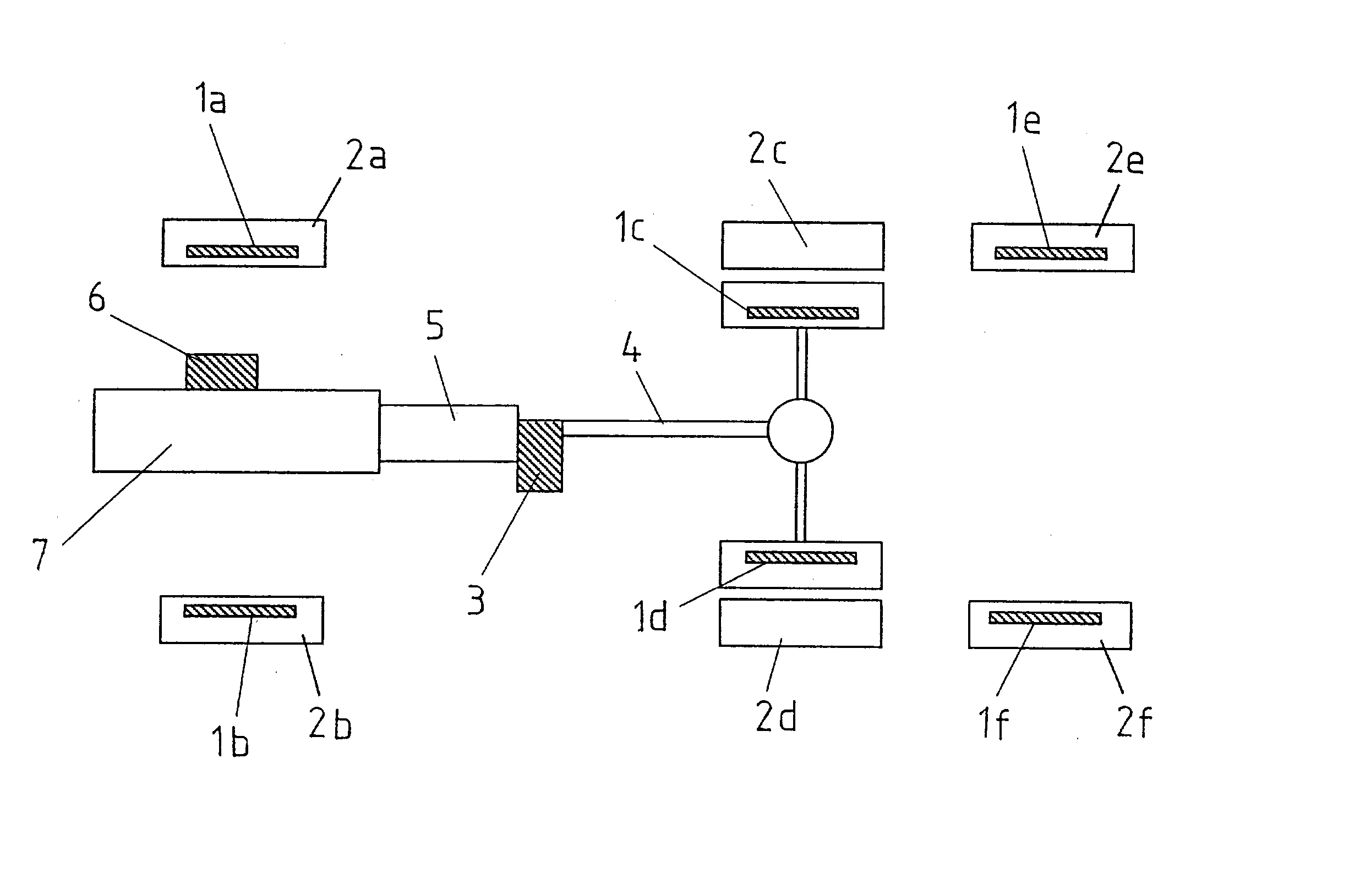
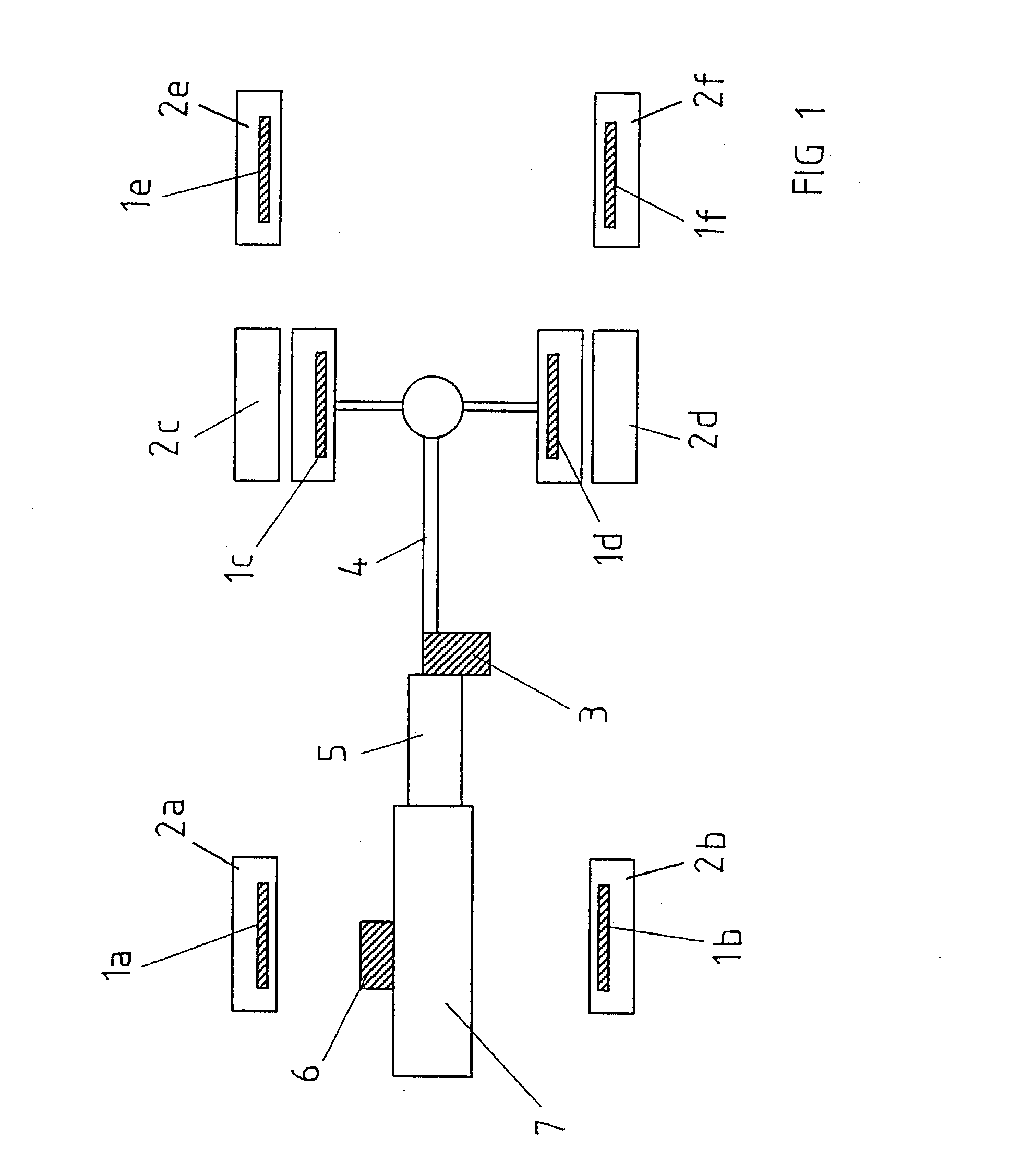
[0022] FIG. 1 depicts schematically the location of the available brakes on a heavy vehicle such as a truck. The vehicle contains a main brake, which includes braking devices 1a-f arranged to act on the vehicle wheels 2a-f. The braking devices 1a-f can consist of pneumatic disc brakes, and in this case the main brake comprises the equipment needed to press the brake pads of the respective disc brakes against the discs that rotate with the wheels 2a-f in question. The vehicle contains an auxiliary brake in the form of a retarder 3 that generates outgoing braking torque using viscous friction. The retarder 3 can be of the type described in the introductory description. The retarder 3 is thus connected to the propeller shaft 4 and to the vehicle gearbox 5 and brakes only the driven wheels 2c-d. The vehicle also contains a further auxiliary brake in the form of an exhaust brake 6. The exhaust brake 6 can be of the type described in the introductory description. The exhaust brake 6 is co...


PUM


Abstract

The invention relates to a device for controlling a braking arrangement on a heavy vehicle. The braking arrangement comprises a main brake, which includes braking devices (1a -f), for example disc brakes, that are each arranged to act on one of the vehicle wheels (2a-f). Furthermore, the braking arrangement comprises at least one auxiliary brake (3) and a brake control (10) with which the named main brake (1a-f) and auxiliary brake (3) are activated. When a driver activates the brake control (10), a control unit (9) in the arrangement is arranged to initiate activation of the main brakes (1a-f) and the auxiliary brake (3) and thus distributes the braking effect between these brakes in such a way that the braking effect requested by the driver is obtained in the shortest possible time and in such a way that the use of the brake devices (1a-f) of the main brake is minimised after an initial period. The invention relates to a braking system for a heavy vehicle, which comprises an arrangement described above.

Description

BACKGROUND OF THE INVENTION AND STATE OF THE ART[0001] This invention relates to a device for controlling a brake arrangement on a heavy vehicle according to patent claim 1.[0002] The brakes on heavy vehicles, for example trucks, function using wheel brakes, which can for example be drum brakes or disc brakes.[0003] When the brakes are applied for a long period, such as when descending a long hill, there is a risk of so-called heat fading, i.e. a reduction in the braking effect because the brake linings become very heated. The wheel brakes on heavy vehicles are usually applied using compressed air and if the wheel brakes are often released and applied during a long period of braking, the requirements on the air system are stringent. There is a risk that the air control pressure can drop, which results in a reduction in the braking effect. On traditional trucks the air passes from a reservoir to the brake chambers at a pressure that is decided by the force exerted on the brake pedal ...

Claims


Application Information

Patent Timeline
Patent Type & Authority Applications(United States)
IPC IPC(8): B60T8/17B60T13/58
CPCB60T13/585
Inventor ANDERSSON, HAKANENGELKE, PETERVAGSTEDT, NILS-GUNNARHEDSTROM, LARS-GUNNARBORTOLIN, GIANANTONIOGUTMAN, PER-OLOF
Owner SCANIA CV AB
Why Eureka
Try Eureka