Write head driver circuit and method for writing to a memory disk

a write head and memory disk technology, applied in the field of circuits and methods for writing to memory disks, can solve problems such as reducing the effective rate at which data can be accurately written and read, and difficulty in distinguishing successive magnetic transitions

Inactive Publication Date: 2003-05-15
STMICROELECTRONICS SRL
View PDF18 Cites 20 Cited by
  • Summary
  • Abstract
  • Description
  • Claims
  • Application Information

AI Technical Summary

Problems solved by technology

Since the disk is moving relative to the head, it can be seen that if the small space separating the magnetic domain transitions is not sufficiently wide, difficulty may be encountered in distinguishing successive magnetic transitions.
This may result in errors in reading the data contained on the disk, which is, of course, undesirable.
However, since the data signals are in the form of square wave transitions, if the rise time of the leading edges of the square waves is large, the small space between magnetic media transitions also becomes large, which reduces the effective rate at which data can be accurately written and read.
Since the write head assembly includes at least one coil, forcing the current to rise rapidly, or to reverse flux directions within the write

Method used


Image

  • Write head driver circuit and method for writing to a memory disk
  • Write head driver circuit and method for writing to a memory disk
  • Write head driver circuit and method for writing to a memory disk

Examples


Embodiment Construction

[0027] The present invention will now be described more fully hereinafter with reference to the accompanying drawings in which exemplary embodiments of the invention are shown.

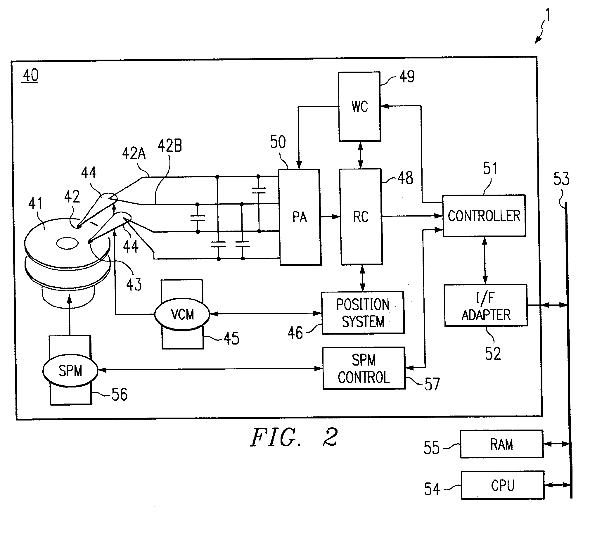
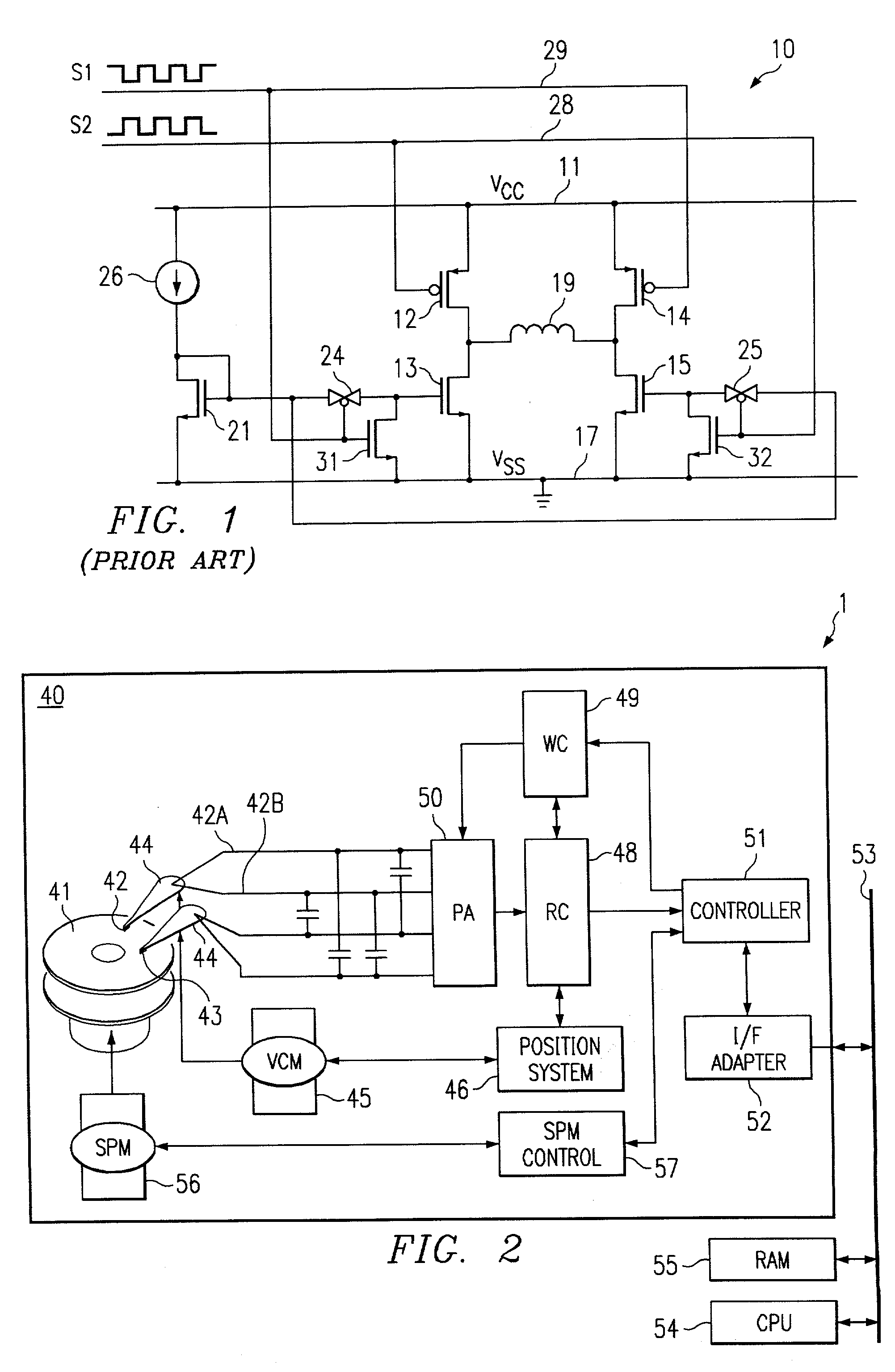
[0028] Referring to FIG. 2, there is shown a block diagram of a data storage, information processing and / or computer system 1 including a disk drive 40 in accordance with the present invention. Disk drive 40 includes a storage medium in the form of one of more disks 41, each of which may contain data on both sides of the disk. Data is written to disks 41 using one or more write heads 42, and read therefrom by one or more read heads 43. Each write head 42 and read head 43 is connected to an arm 44 and is positionally controlled by a voice-coil motor ("VCM") 45 and a position system 46. The position system 46, through VCM 45, positionally maintains and / or moves write head 42 and read head 43 radially over the desired data on disks 41. A read channel 48 converts an analog read signal from read head 43 into digita...


PUM


Abstract

A circuit and method are disclosed for relatively rapidly causing the current flowing through a write head to transition between steady states without generating an appreciable amount of capacitively-coupled noise. Embodiments of the present invention generally provide drive voltage signals to the write head that have no common mode voltage levels during transitions between steady state current levels in the write head. In other words, the drive voltage signals applied to the write head are substantially entirely differential during write head current transitions. In an exemplary embodiment of the present invention, a driver circuit includes switching circuitry connected between the terminals of the write head and reference voltage supplies, such as positive and negative voltage supplies. The driver circuit further includes timing circuitry that generates control signals for controlling the switching circuitry.

Description

[0001] This application is related to U.S. patent application Ser. No. 09 / 651,830, filed Aug. 30, 2000, entitled "METHOD FOR DIFFERENTIALLY WRITING TO A MEMORY DISK" (Docket No. 00-S-47); and to U.S. patent application Ser. No. 09 / 651,561, filed Aug. 30, 2000, entitled "WRITE HEAD DRIVER CIRCUIT AND METHOD FOR WRITING TO A MEMORY DISK" (Docket No. 00-S-48).[0002] 1. Technical Field of the Invention[0003] The present invention relates to circuit and method for writing to a memory disk, and particularly to a circuit and method for differentially driving the write head of a disk drive device.[0004] 2. Background of the Invention[0005] Most computer systems include one or more associated disk drives, which may be built into or external to the computer system. Typically, disk drives have at least one rotating magnetic medium and associated head mechanisms that are carried adjacent the magnetic material. The heads are radially positionable to selectively write information to, or read info...

Claims


Application Information

Patent Timeline
IPC IPC(8): G11B5/09G11B5/00G11B5/012G11B5/02
CPCG11B5/012G11B5/02G11B2005/0013G11B5/09G11B5/022
Inventor VENCA, ALESANDROPOSAT, BARISOZANOGLU, KEMALALINI, ROBERTO
Owner STMICROELECTRONICS SRL
Why Eureka
Try Eureka