Mechanical face seal for materials handling apparatus

a technology of face seals and mechanical components, applied in mechanical components, mechanical equipment, chemistry equipment and processes, etc., can solve problems such as tend to wear very quickly

Inactive Publication Date: 2003-05-29
MANSDORFER GARY A
View PDF3 Cites 2 Cited by
  • Summary
  • Abstract
  • Description
  • Claims
  • Application Information

AI Technical Summary

Problems solved by technology

A particular problem is the ability to maintain effective, uniform sealing between the annular rotor and stator parts in a contaminated environment and with minimal wear.
The seals are typically effective for a short period of time and tend

Method used


Image

  • Mechanical face seal for materials handling apparatus
  • Mechanical face seal for materials handling apparatus
  • Mechanical face seal for materials handling apparatus

Examples


Embodiment Construction

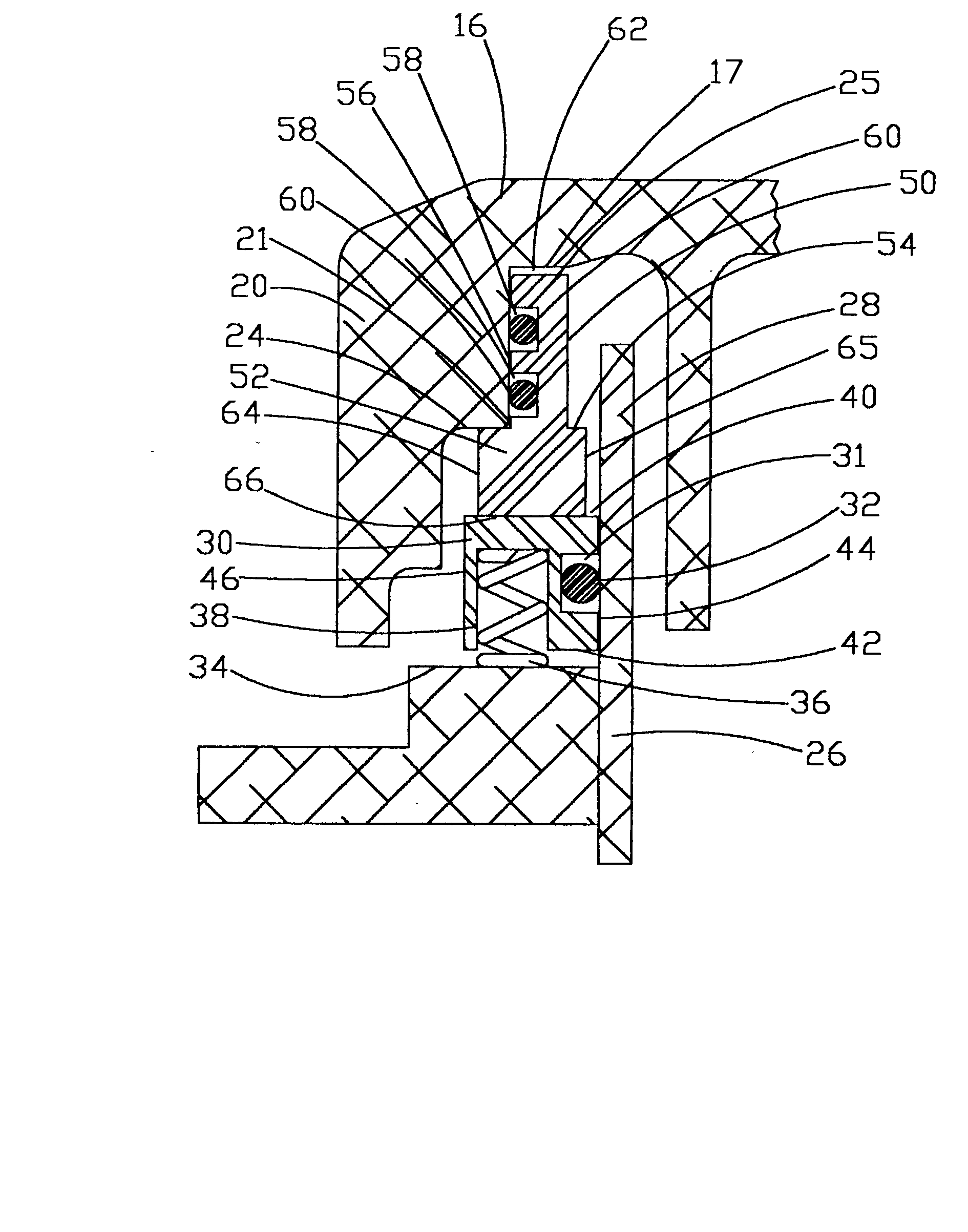
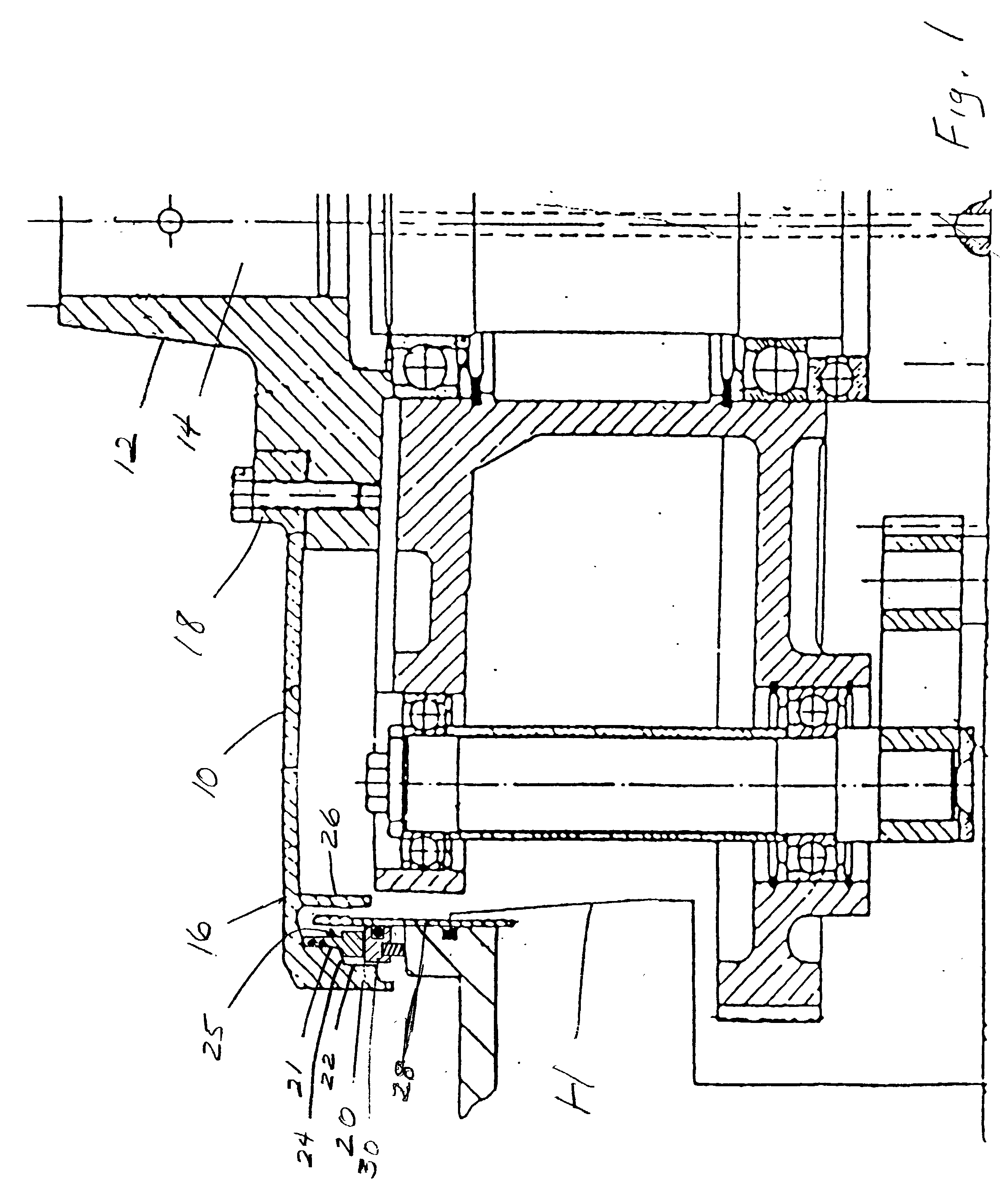
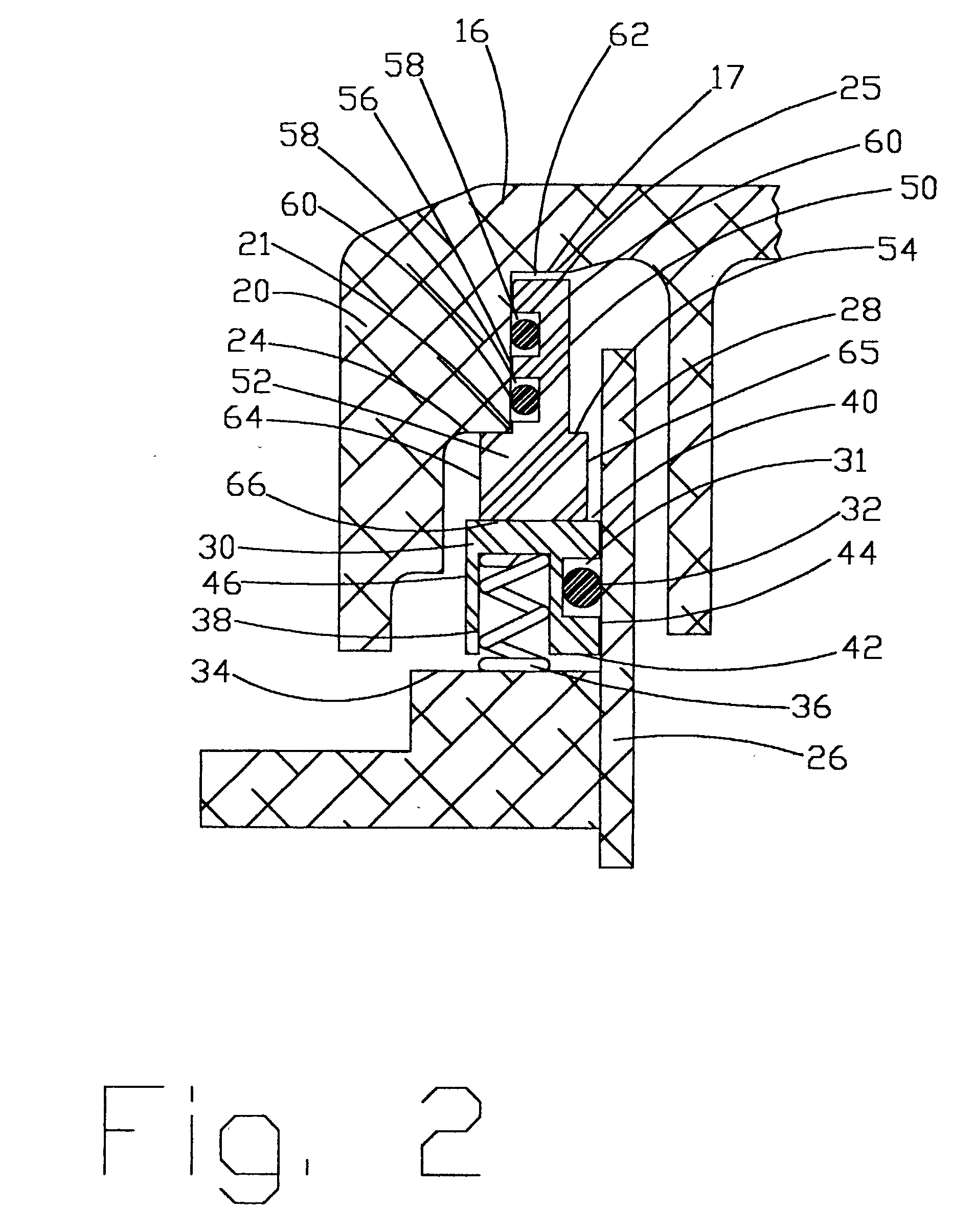
[0015] Referring to FIG. 1, there is shown by way of example a conventional rotary drive mechanism for a turntable or cover 10 of a labeling machine for bottles. The turntable is mounted on a hub 12 for rotation about a vertical axis through a main drive shaft 14 which is suitably driven by a motor, not shown. The turntable 10 has a generally circular cover 16 which is fastened as at 18 to the hub 12, and the cover 16 terminates in an outer downwardly projecting skirt 20 having inner stepped wall surfaces 21 and 22 interconnected by a shoulder or radial surface 24 for mounting of a preferred form of rotor which is defined by an upper face seal portion 25. The lid also includes a downwardly projecting flange 26 in spaced inner concentric relation to the skirt 20.

[0016] Further by way of illustrative example, the cover 16 forms the upper end of a housing generally designated at H for the various component parts of the drive mechanism for the labeling machine and which is at least part...


PUM

PropertyMeasurementUnit
Resilienceaaaaaaaaaa
Frictionaaaaaaaaaa

Abstract

In materials handling apparatus, such as, a bottle labeling machine of the type having annular rotating and fixed members in confronting relation to one another, a facial seal assembly is made up of first and second seal members between the rotating and fixed members which are of generally rectangular cross-sectional configuration and terminate in squared end portions defining relatively broad, flat annular bearing surfaces in flush sealed relation to one another as the turntable is rotated or driven with respect to the stationary mounting portion and prevents ingress and egress of liquid as well as solid materials to and from the interior of the apparatus.

Description

[0001] This application claims the benefit of Provisional Serial No. 60 / 336,400, filed 28 Nov. 2001, for MECHANICAL FACE SEAL FOR MATERIALS HANDLING APPARATUS by Gary A. Mansdorfer and owned by the assignee of the present application.BACKGROUND AND FIELD OF INVENTION[0002] This invention relates to seals, and more particularly relates to a mechanical face seal of annular configuration primarily intended for use in conjunction with materials handling apparatus, such as, the rotary drive of a container labeling machine.[0003] There are numerous applications where a system requires a seal between relatively rotating members or in which one member is rotating and the other one is fixed. For example, in labeling machines for bottles there is a need for a seal between annular rotor and stator members which will efficiently prevent oil or lubricant from leaking out of the system as well as to prevent liquid or solid contaminants from reaching the interior of the machine. Representative of ...

Claims


Application Information

Patent Timeline
IPC IPC(8): F16J15/34
CPCY10T156/1744F16J15/3496
Inventor MANSDORFER, GARY A.
Owner MANSDORFER GARY A
Why Eureka
Try Eureka