Hybrid compressor device

a hybrid compressor and compressor technology, applied in the direction of positive displacement liquid engines, piston pumps, lighting and heating apparatus, etc., can solve the problems of increasing the production cost of the hybrid compressor device and preventing the heat exchange efficiency reduction of the heat exchanger

Inactive Publication Date: 2003-06-05
NIPPON SOKEN +1
View PDF7 Cites 10 Cited by
  • Summary
  • Abstract
  • Description
  • Claims
  • Application Information

AI Technical Summary

Problems solved by technology

However, the hybrid compressor device requires the solenoid clutch for switching a driving source of the compressor between the engine in the operation of the engine, and the motor in the stop of the engine.
Therefore, production cost of the hybrid compressor device is increased.
Therefore, lubrication oil is not adhered to a heat exchanger such as an evaporator provided in the refrigerant cycle system, thereby preventing heat-exchange efficiency of the heat exchanger from being reduced.

Method used


Image

  • Hybrid compressor device
  • Hybrid compressor device
  • Hybrid compressor device

Examples


first embodiment

[0035] (First Embodiment)

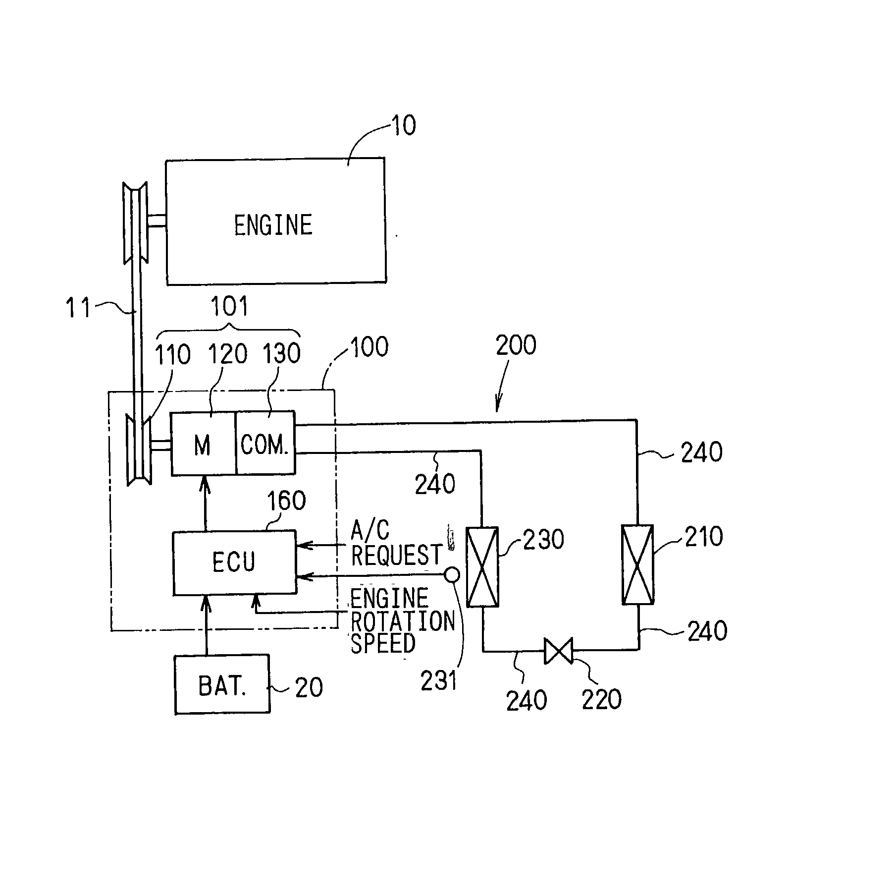
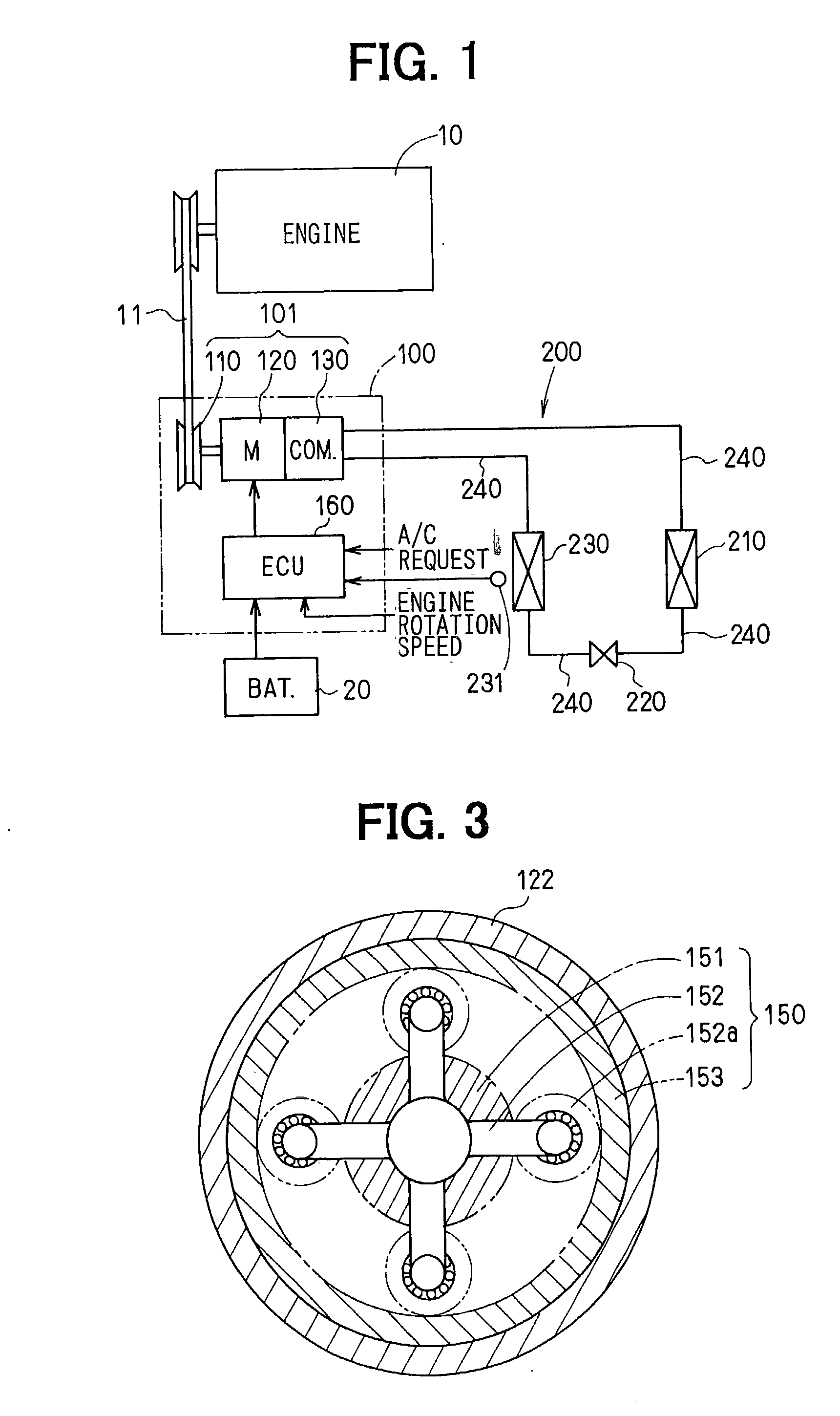
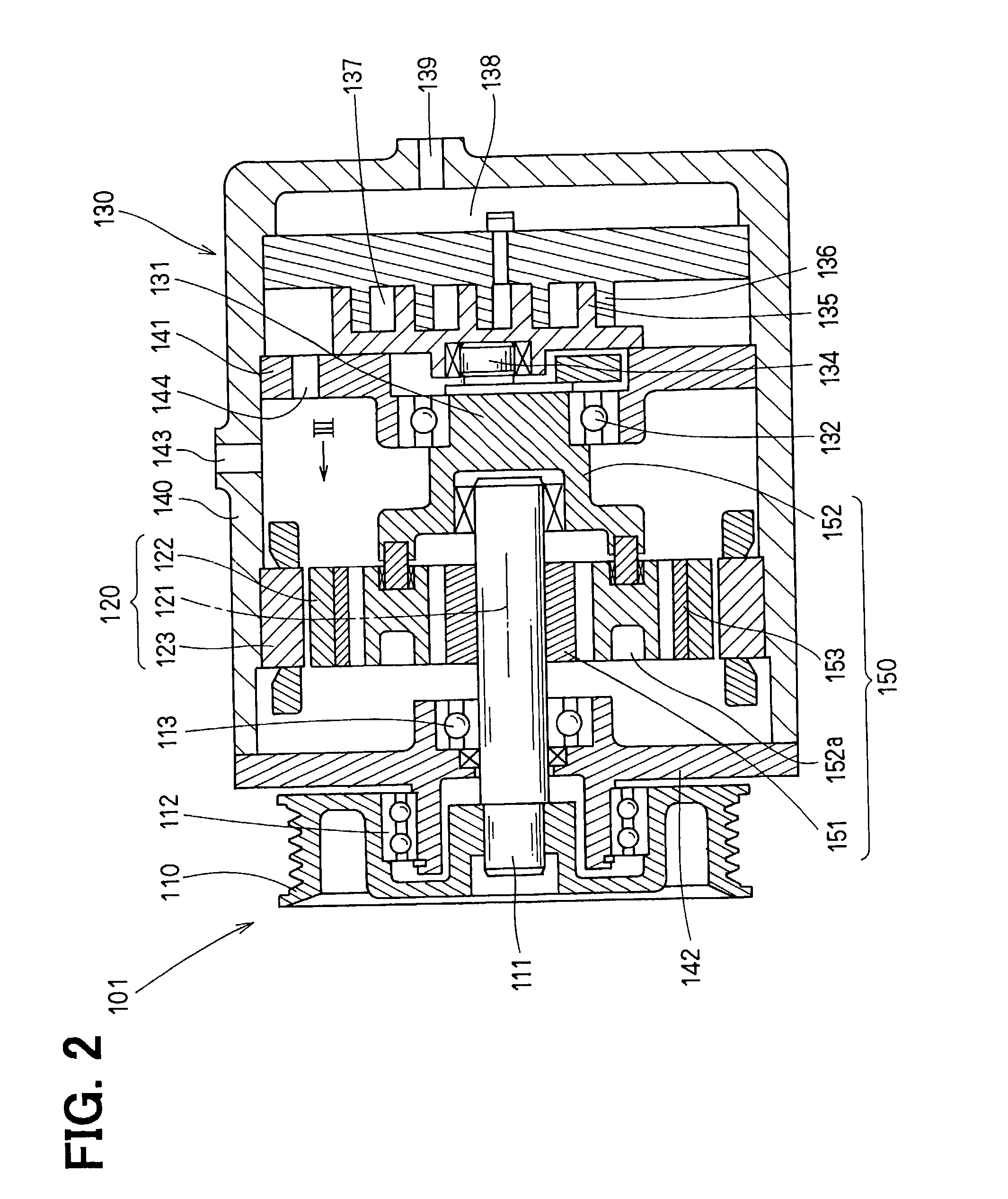
[0036] The first embodiment of the present invention will be now described with reference to FIGS. 1-5. In FIG. 1, a hybrid compressor device 100 is typically applied to a refrigerant cycle system 200 mounted in an idling stop vehicle where a vehicle engine 10 is stopped when the vehicle is temporally stopped. The hybrid compressor device 100 includes a hybrid compressor 101 and a control unit 160. The refrigerant cycle system 200 includes components such as a compressor 130, a condenser 210, an expansion valve 220 and an evaporator 230. The components are sequentially connected by refrigerant piping 240, to form a closed circuit. The compressor 130 constructs the hybrid compressor 101. The compressor 130 compresses refrigerant, circulating in the refrigerant cycle system, to a high temperature and high pressure. The compressed refrigerant is condensed in the condenser 210, and the condensed refrigerant is adiabatically expanded by the expansion valve 220. T...

second embodiment

[0052] (Second Embodiment)

[0053] The second embodiment of the present invention will be now described with reference to FIGS. 6 and 7.

[0054] In the second embodiment, as shown in FIG. 6, the planetary gear 150 is disposed in a rotor portion 120a of the motor 120, and the pulley rotational shaft 111, the rotation shaft of the motor 120 and the compressor rotational shaft 131 are connected to the planetary gear 150, as compared with the first embodiment. Further, a solenoid clutch 170 and a one-way clutch 180 are added to the hybrid compressor 101 as compared with the first embodiment. Here, a surface permanent-magnet motor (SP motor), where permanent magnets are provided on an outer periphery of the rotor portion 120a, is used as the motor 120. The planetary gear 150 is disposed in a space of the rotor portion 120a on the inner periphery side. The pulley rotational shaft 111 is connected to the planetary carriers 152, and the rotor portion 120a of the rotor 120 is connected to the su...

third embodiment

[0061] (Third Embodiment)

[0062] The third embodiment of the present invention will be now described with reference to FIGS. 8 and 9. As shown in FIG. 8, in the third embodiment, an another one-way clutch (second one-way clutch) 190 is added to the hybrid compressor 101, as compared with the second embodiment. The second one-way clutch 190 allows the motor 120 to rotate only in the inverse rotational direction from the rotational direction of the pulley 110. The second one-way clutch 190 is disposed between the rotor portion 120a of the motor 120 and the housing 140.

[0063] In the third embodiment, the operation of the hybrid compressor 101 is different from the second embodiment in the normal cooling mode after the cool down mode, among the cool down mode, the normal cooling mode after the cool down mode, the cooling mode in the stop of the engine 10 and the cooling mode in the operation of the engine 10. As shown by the straight line G in FIG. 9 (corresponding to the straight line G...


PUM


Abstract

In a hybrid compressor for a vehicle where a vehicle engine is stopped when the vehicle is temporally stopped, a pulley, a motor and a compressor can be driven in independent from each other, and are connected to a sun gear, planetary carriers and a ring gear of a planetary gear. A rotational speed of the motor is adjusted by a controller, so that a rotational speed of the compressor is changed with respect to a rotational speed of the pulley. Accordingly, production cost of the hybrid compressor and the size thereof can be reduced, while a cooling function can be ensured even when the vehicle engine is stopped.

Description

[0001] This application is related to and claims priority from Japanese Patent Applications No. 2001-366706 filed on Nov. 30, 2001, No. 2002-196053 filed on Jul. 4, 2002, No. 2002-223638 filed on Jul. 31, 2002, and No. 2002-284142 filed on Sep. 27, 2002, the contents of which are hereby incorporated by reference.[0002] 1. Field of the Invention[0003] The present invention relates to a hybrid compressor device suitable for a refrigerant cycle system mounted in an idling stop vehicle, where a vehicle engine is stopped when the vehicle is temporally stopped.[0004] 2. Description of Related Art[0005] Recently, the market for an idling stop vehicle has been increased to save fuel consumption. In a case where a compressor is driven only by an engine of the vehicle, when the vehicle is temporarily stopped, its engine is stopped, so that the compressor, driven by the engine, is also stopped in a refrigerant cycle system. In order to overcome this problem, in a conventional hybrid compressor...

Claims


Application Information

Patent Timeline
Patent Type & Authority Applications(United States)
IPC IPC(8): F04B27/08F04B35/00F04B35/04F04B17/03F04C28/08F04C29/00F25B27/00F25B49/02
CPCF04B27/0895F04B35/002F04B35/04F04C28/08F25B2600/025F04C2240/45F25B27/00F25B49/025F25B2327/001F04C29/0085F04B17/03
Inventor SUZUKI, YASUSHIIWANAMI, SHIGEKIASA, HIRONORIUNO, KEIICHI
Owner NIPPON SOKEN
Why Eureka
Try Eureka