Active fuel cap sensor using magnetic impulse detection

a fuel cap sensor and magnetic impulse technology, applied in the direction of burglar alarm mechanical actuation, instruments, packaged goods types, etc., can solve the problems of inability to reliably detect magnetic sensors over wide temperature ranges, inconvenient assembly of the prior art fuel cap sensor assembly, and inability to accurately determine the position of the locking fuel cap according to this principl

Inactive Publication Date: 2003-06-05
LAVALLEE ROGER
View PDF13 Cites 19 Cited by
  • Summary
  • Abstract
  • Description
  • Claims
  • Application Information

AI Technical Summary

Benefits of technology

0012] The present invention preserves the advantages of prior art fuel cap sensor assemblies which employ magnetic switches, such as reed relays. In addition, it provides new advantages not found in currently available assemblies and overcomes many disadvantages of such currently available assemblies.

Problems solved by technology

Since the magnetic field of the magnets cannot be localized to a narrow limited space, the position of the locking fuel cap can be determined only relatively inaccurately according to this principle.
However, while desirable from a performance and cost standpoint, magnetic sensors do not perform reliably over wide temperature ranges, particularly at low temperatures.
Under low temperature conditions, the magnetic switch prematurely operates to falsely indicate that the fuel cap has been tightly closed when it, in fact, has not.
Therefore, the aforementioned fuel cap sensor assembly of the prior art is undesirable as it unreliably indicates a safe tightened fuel cap condition.
Subsequently, if the locking fuel cap is screwed back once again onto the tank connection pipe, the magnetic switch remains open, since the force of the magnet alone is insufficient for bringing the reed contacts into the closed position.
However, this prior art assembly is still unreliable due to the well known unpredictability and temperature sensitivity of magnetic switches and, namely, the hysteresis characteristics thereof.

Method used


Image

  • Active fuel cap sensor using magnetic impulse detection
  • Active fuel cap sensor using magnetic impulse detection
  • Active fuel cap sensor using magnetic impulse detection

Examples


Embodiment Construction

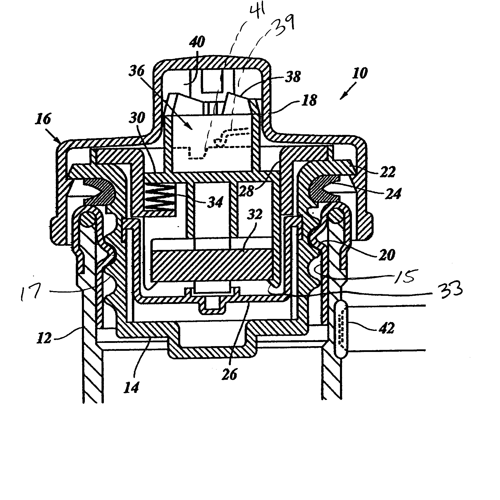
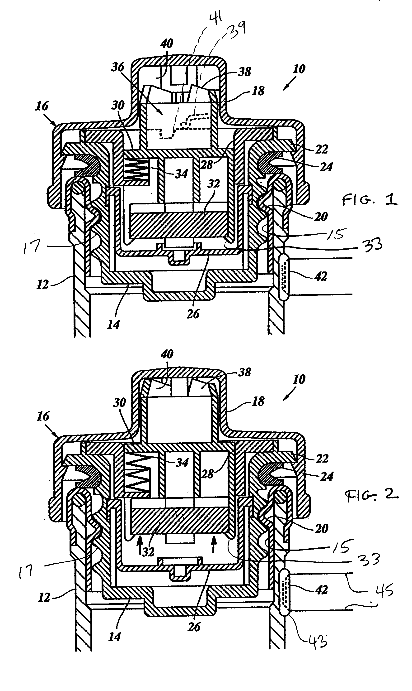
[0025] Turning first to Fig. 1, a locking fuel cap 10 is screwed onto a connection pipe 12 of a fuel tank of a vehicle (now shown). The locking fuel cap 10 has a screw-in plug 14 and a cap 16, which is connected rotatably with the screw-in plug 14 and forms a handle 18. In the opening 15 of the tank connection pipe 12, a threaded insert 20 is fastened, which has engaged the external thread 17 of the screw-in plug 14. Fig. 1 shows the locking fuel cap 10 in the closed position, in which a flange 22 of the screw-in plug, over a seal 24, is in sealing contact with the edge of the threaded insert 20.

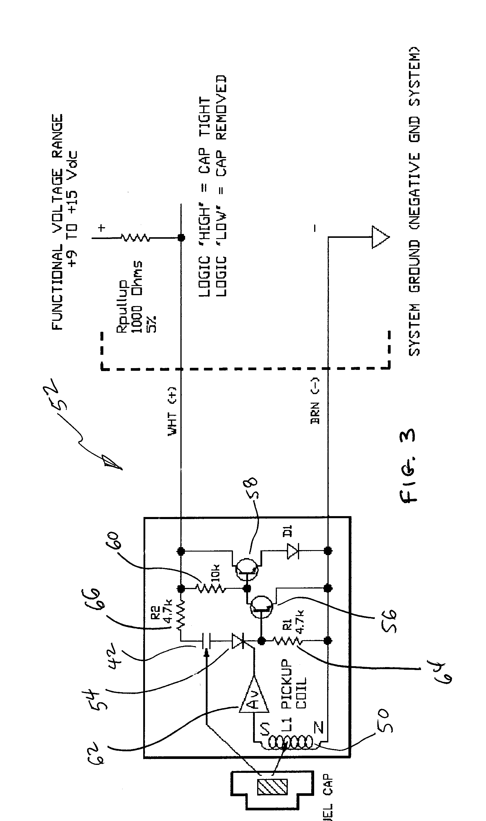
[0026] In the interior of the screw-in plug 14, a pot-shaped inner part 26 and, further to the outside, that is, further towards the top in Fig. 1, a guiding bush 28 is disposed, in which a magnet carrier 30 is movably guided in a axial direction. A magnet 32, such as a permanent magnet, is held with holding claws 33 at the magnet carrier 30 and lies within the pot-shaped inner part 26. The ...


PUM

PropertyMeasurementUnit
magnetic field strengthaaaaaaaaaa
voltageaaaaaaaaaa
magnetic fieldaaaaaaaaaa

Abstract

Abstract of Disclosure An apparatus and circuit for monitoring the closed position of a fuel cap relative to a tank connection pipe . The fuel cap has a ratchet torque limiter for controlling the tightening of the fuel cap to the tank connection pipe. A magnet is connected to the fuel cap and a magnetic switch, such as a reed switch, is connected to the tank connection pipe or proximal thereto. The movement of the magnet relative to the magnetic switch, indicating a locked fuel cap condition, is sensed by an abrupt change in magnetic field strength of the magnet. When releasing members snap over the cams therein, a current pulse is induced in a pickup coil . This current pulse is sensed and a logic level high voltage is produced corresponding to a tightened fuel cap condition. A dashboard lamp is then extinguished indicated that the fuel cap is safely and securely tightened.

Description

Cross Reference to Related Applications[0001] This application is related to and claims priority from earlier filed provisional patent application Serial No. 60 / 337,021, filed December 3, 2001.Background of Invention[0002] The invention relates to an apparatus, assembly and method for monitoring the closed position of a locking fuel cap, with a magnet disposed in the locking fuel cap and a magnetic switch disposed at or proximal to a tank connection pipe.[0003] There have been many attempts in the prior art to monitor the position of the locking fuel cap of a motor vehicle so that, when the locking fuel cap is not closed or closed incompletely, a warning signal appears on the dashboard of the vehicle.[0004] For example, various prior art locking fuel caps have a bayonet catch and the magnet is disposed in such a manner, that it is in the vicinity of a reed switch when the bayonet catch is locked. Depending on the construction, the reed switch is thus either open or closed when the l...

Claims


Application Information

Patent Timeline
Patent Type & Authority Applications(United States)
IPC IPC(8): B60Q1/00B65B3/00G08B21/00
CPCB60K2015/0319B60K15/0406
Inventor LAVALLEE , ROGER
Owner LAVALLEE ROGER
Why Eureka
Try Eureka