High-temperature behavior of the trailing edge of a high pressure turbine blade

a high-temperature behavior, high-pressure turbine technology, applied in the direction of machines/engines, mechanical equipment, liquid fuel engines, etc., can solve the problems of poorly cooled slots closest to the root of the blade, harmful to the lifetime of the blade, etc., and achieve the effect of lowering the temperature of the connection zon

Inactive Publication Date: 2003-06-12
SN DETUDE & DE CONSTR DE MOTEURS DAVIATION S N E C M A
View PDF5 Cites 3 Cited by
  • Summary
  • Abstract
  • Description
  • Claims
  • Application Information

AI Technical Summary

Benefits of technology

0010] In order to lower the temperature of a connection zone between the root of the blade and a platform defining the flow stream of combustion ga

Problems solved by technology

Unfortunately, in practice, it is found that the slot closest to the root of the blade is poorly cooled.
As a result large temperature gradients aris

Method used


Image

  • High-temperature behavior of the trailing edge of a high pressure turbine blade
  • High-temperature behavior of the trailing edge of a high pressure turbine blade

Examples


Embodiment Construction

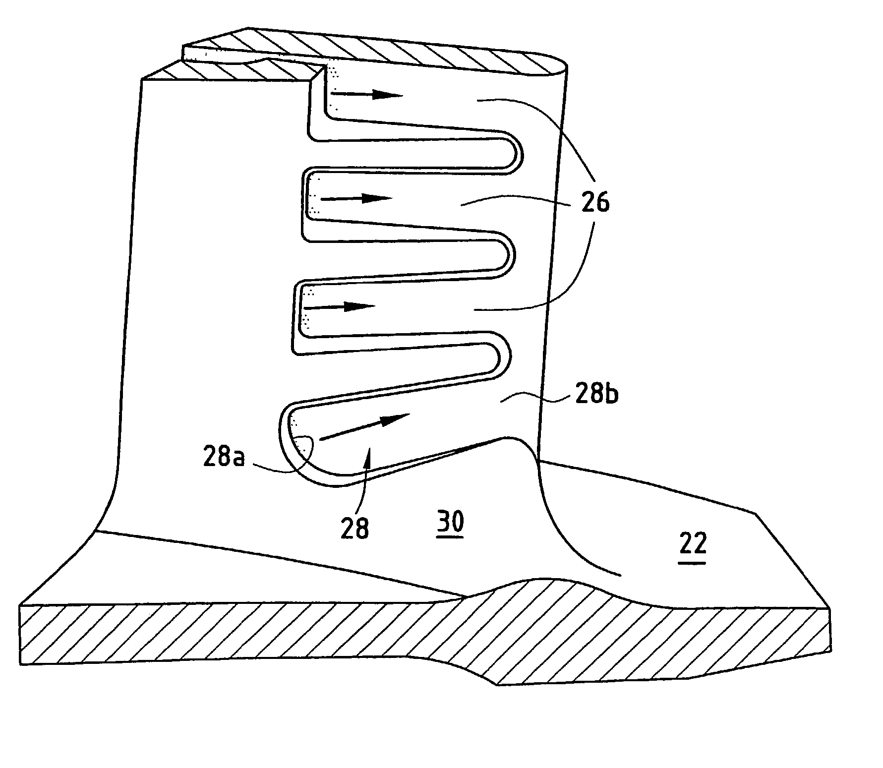
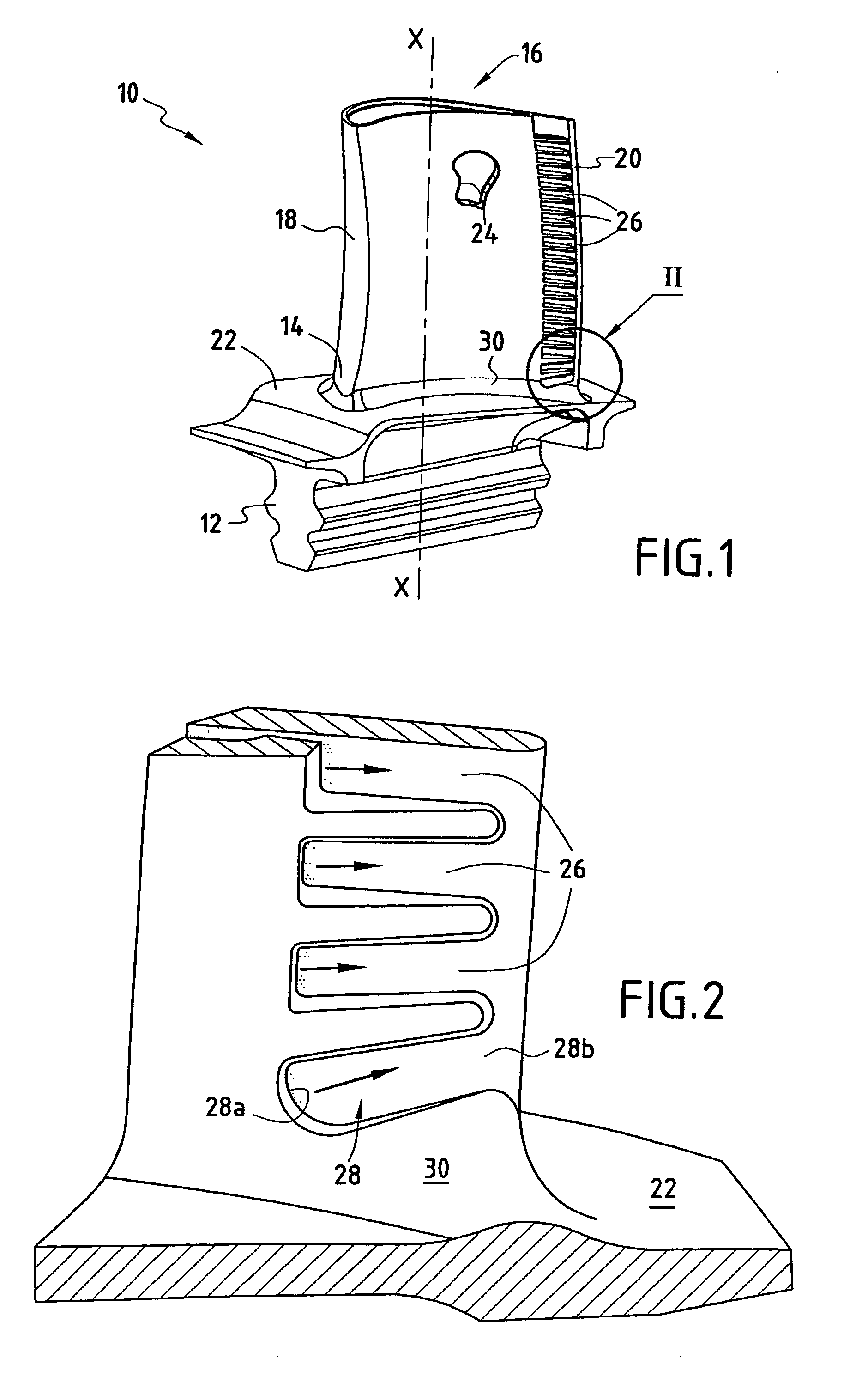
[0014] FIG. 1 is a perspective view of a moving blade 10, e.g. for a high pressure turbine of a turbomachine. This blade has a longitudinal axis X-X and it is fixed to a rotor disk (not shown) of the high pressure turbine via a generally firtree shaped shank 12. It typically comprises a root 14, a tip 16, a leading edge 18, and a trailing edge 20. The shank 12 is connected to the root 14 of the blade via a platform 22 which defines a wall for the flow stream of combustion gases through the high pressure turbine.

[0015] Such a blade is subjected to the very high temperatures of combustion gases and it needs to be cooled. For this purpose, and in conventional manner, the moving blade 10 has at least one internal cooling circuit. This cooling circuit is constituted, for example, by at least one cavity 24 extending radially between the root 14 and the tip 16 of the blade. This cavity is fed with cooling air from one of its radial ends via an air admission opening (not shown). This air ad...


PUM


Abstract

A moving blade for a high pressure turbine of a turbomachine, the blade having at least one cooling circuit comprising at least one cavity extending radially between a tip and a root of the blade, at least one air admission opening at one of the radial ends of the cavity(ies) to feed the cooling circuit(s) with cooling air, and a plurality of slots opening out from the cavity(ies) and into the trailing edge of the blade, the slots being arranged along the trailing edge between the root and the tip of the blade in a manner that is substantially perpendicular to a longitudinal axis of the blade, at least the slot closest to the root of the blade presenting an inclination towards the tip of the blade lying in the range 10° to 30° relative to an axis of rotation of the blade.

Description

[0001] The present invention relates to the field of moving blades for the high pressure turbine of a turbomachine, and more particularly it relates to slots for exhausting cooling air that are situated in the trailing edges of the moving blades of a high pressure turbine.[0002] In conventional manner, a turbomachine has a combustion chamber in which air and fuel are mixed together prior to being burnt therein. The gas that results from this combustion flows downstream inside the combustion chamber and then feeds a high pressure turbine. The high pressure turbine has one or more rows of moving blades spaced apart circumferentially all around the rotor of the turbine. The moving blades of the high pressure turbine are thus subjected to the very high temperatures of the combustion gases. These temperatures reach values well above those which can be withstood without damage by the blades that come into contact with said gas, thereby shortening their lifetime.[0003] In order to solve th...

Claims


Application Information

Patent Timeline
IPC IPC(8): F01D5/18
CPCF01D5/187
Inventor BARIAUD, CHRISTIANBOURY, JACQUES
Owner SN DETUDE & DE CONSTR DE MOTEURS DAVIATION S N E C M A
Why Eureka
Try Eureka