Laser consolidation apparatus for manufacturing precise structures

a technology of precise structure and laser, which is applied in the direction of additive manufacturing processes, soldering apparatus, manufacturing tools, etc., can solve the problems of poor quality of cladding perpendicular to the flow, inflexible metal selection, and poor quality of cladding

Inactive Publication Date: 2003-06-26
NAT RES COUNCIL OF CANADA
View PDF4 Cites 57 Cited by
  • Summary
  • Abstract
  • Description
  • Claims
  • Application Information

AI Technical Summary

Problems solved by technology

A major limitation of the SLS process is its inflexibility in the selection of metals that can be used.
The process requires that after each laser build-up pass, the metal layer is machined back to required dimensions, necessary because of a lack of control on the laser build-up.
Good quality clad with a regular shaped bead was obtained parallel to the flow direction but as the angle to the flow direction increased the quality deteriorated until clad perpendicular to the flow was of poor quality.
As side nozzle powder delivery builds unevenly in various directions in the xy-plane, the additional required step of machining after each deposition pass makes the process cumbersome and expensive.
As the control on the build-up process is poor, most of the material is removed to maintain the geometry creating unnecessary waste of expensive material.
Ministry does not teach the importance of the critical angle of the lasers relative to the powder feed nozzle, the symmetrical arrangement of the laser beams relative to the material feed system nor the control over and the shape of the melt pool required to make precise structures and components with smooth walls.
The arrangement is symmetrical but powder entering from the sides causes thermal and viscosity gradients 22, leading to incomplete melting where the wall surfaces are forming.
Attempting to correct the situation by adding more energy is not successful because the surface where the energy enters starts to evaporate causing a plasma to form which absorbs the incoming laser energy.
When material is added and melted into the melt pool, to increase its volume, it is more difficult to maintain a smooth finish.
The problems with existing state of the art near net shape processes that feed powder into the pool from the sides stem from the thermal, and hence viscosity gradients, created in the pool and from powder particles sticking to the side walls as the pool solidifies.
However, in practice there may be a need to make minor adjustments in wall thickness.

Method used


Image

  • Laser consolidation apparatus for manufacturing precise structures
  • Laser consolidation apparatus for manufacturing precise structures
  • Laser consolidation apparatus for manufacturing precise structures

Examples


Embodiment Construction

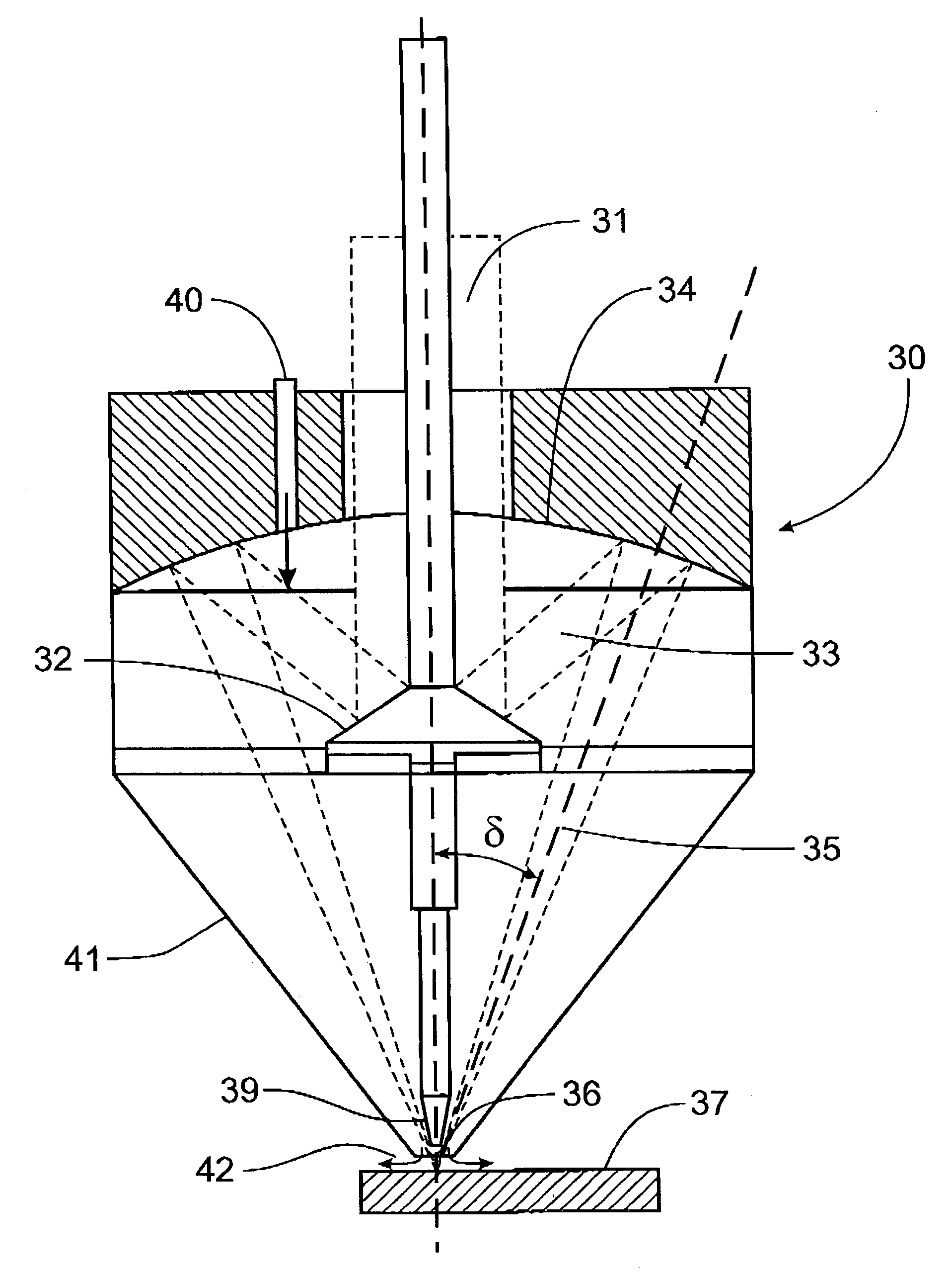
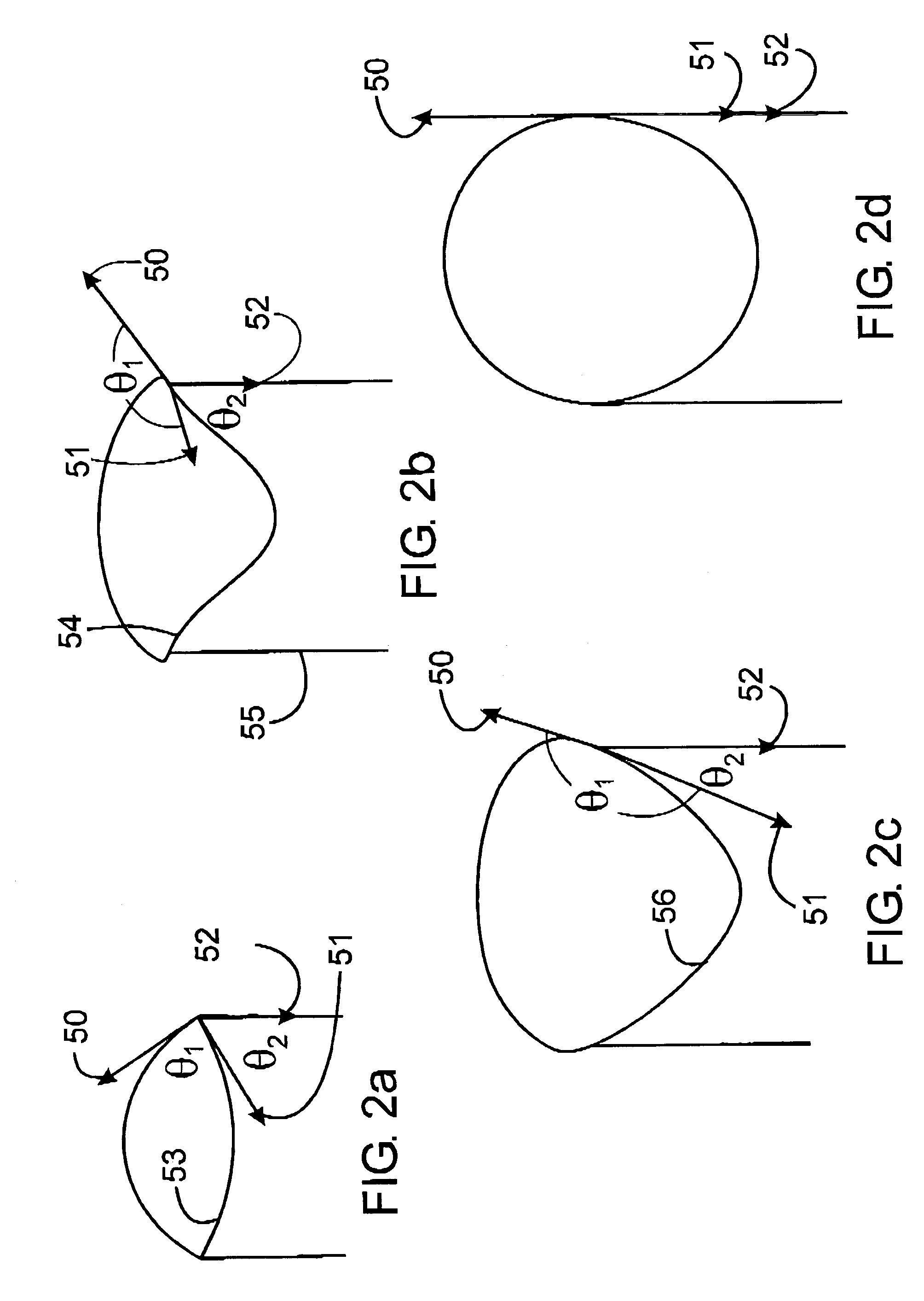
[0043] In building components using the laser consolidation process, the shape and position of the liquid to vapour and the liquid to solid surface tension interfaces are critical.

[0044] Using the consolidation process to create precise structures with smooth sides, requires the volume of molten material to be as close to spherical as possible where the diameter of the sphere is equal to the thickness of the wall under construction. It follows that the process depends on being able to control the diameter and location of the sphere.

[0045] It is well known that when a liquid body is free to do so, it minimizes its energy content by assuming a spherical shape. This is the shape that has the least surface area to volume. In practice this is difficult to attain. One example, is when a liquid freezes during a free fall, such as in forming lead shot. It is also possible using the controlled conditions of the consolidation process to create essentially a spherically shaped volume of molten...


PUM

PropertyMeasurementUnit
angleaaaaaaaaaa
angleaaaaaaaaaa
angleaaaaaaaaaa

Abstract

A laser consolidation apparatus for manufacturing precise three dimensional structures disclosed. The apparatus comprises means for feeding a stream of material to an area on a surface to be built up, at an angle normal to the surface and means to direct a converging laser beam on the surface at an angle of 25 to 30° to the normal to the surface from a plurality of directions surrounding the material feed. Discrete mirror segments direct the laser beam on to movable plane mirrors producing reflected beams which combine to illuminate an area on the work surface.

Description

[0001] This application is a continuation-in-part of application Ser. No. 09 / 699,483 filed Oct. 31, 2000 entitled "Laser Consolidation Methodology and Apparatus for Manufacturing Precise Structures" which is a continuation-in-part of application Ser. No. 09 / 408,853 filed Sep. 30, 1999 and entitled "Process for Manufacturing or Repairing Turbine Engine or Compressor Components".STATEMENT REGARDING FEDERALLY SPONSORED RESEARCH / DEVELOPMENT[0002] Not Applicable[0003] 1. Field of the Invention[0004] This invention relates to an apparatus for building precise 3D components and structures by a material addition process called laser consolidation, more particularly an arrangement for the vertical delivery of metallic powder, or wire into a precisely formed melt pool created in a substrate by laser beams having a specific angular orientation relative to the substrate.[0005] 2. Background Information[0006] Rapid Prototyping (RP) is a related technique based on layered manufacturing where a pa...

Claims


Application Information

Patent Timeline
Patent Type & Authority Applications(United States)
IPC IPC(8): B23K26/00B23K26/06B23K26/34B23P6/00B23P15/02B23P15/04F01D5/00
CPCB23K26/0604B23K26/0608B23K26/34B23P6/007B23P15/02B23P15/04B23K35/0244B23K26/3206B23K26/3246B29C67/0077B22F2003/1056B23K35/0255B23K35/228F01D5/005B23K26/32B23K26/324B29C64/153B23K2103/30B23K2103/50B33Y30/00Y02P10/25B22F12/53B22F12/41B22F12/44
Inventor MCGREGOR, GAVINISLAM, MAHMUD-UL
Owner NAT RES COUNCIL OF CANADA
Why Eureka
Try Eureka