DC-DC converter

a converter and dc technology, applied in the direction of testing circuits, process and machine control, instruments, etc., can solve the problems of increasing the production cost of this device, the reliability the inability to meet the compactness of the electrical device,

Inactive Publication Date: 2003-07-03
SANKEN ELECTRIC CO LTD
View PDF1 Cites 17 Cited by
  • Summary
  • Abstract
  • Description
  • Claims
  • Application Information

AI Technical Summary

Problems solved by technology

Therefore, there are questions about reliability of the electrical device including the conventional DC-DC converter in abnormal condition.
Accordingly, the production costs of this device are increased.
Moreover, a large space for mounting a number of the electrical components refuses compactness of the electrical device.
However, in short time, the fuse cuts off this flow to stop operations of the switching element and the DC-DC converter.

Method used


Image

  • DC-DC converter
  • DC-DC converter
  • DC-DC converter

Examples


Embodiment Construction

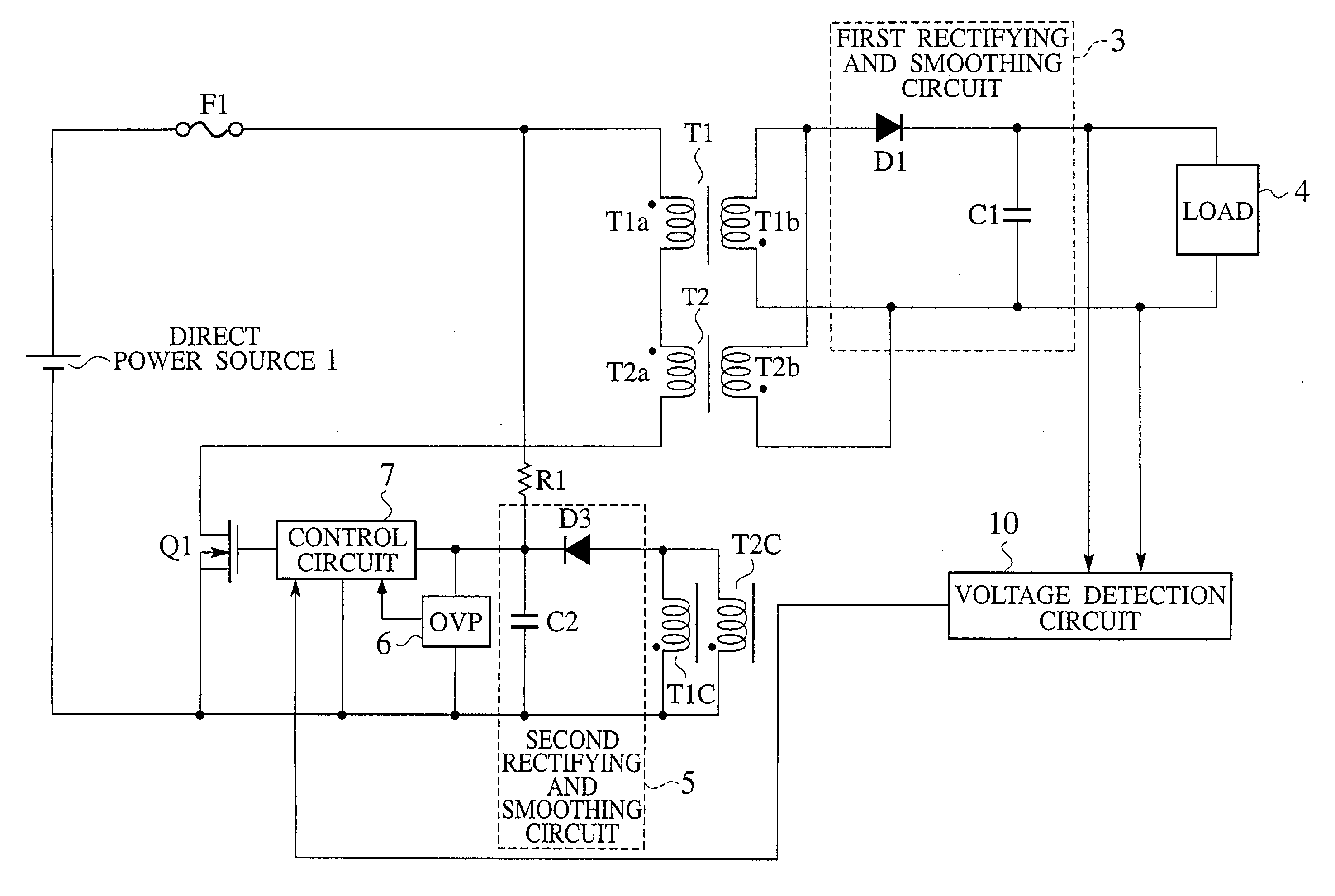
[0067] FIG. 4 is a circuit diagram showing a structure of modified example of DC-DC converter relating to an embodiment of the present invention. According to characteristics of this modified example, as shown in FIG. 4, one end of auxiliary winding T1c is connected in series to an anode of diode D4 of second rectifying and smoothing circuit 5. One end of auxiliary winding T2c is connected in series to an anode of diode D3 of the second rectifying and smoothing circuit 5. Further, cathodes of the diodes D3 and D4 are commonly connected to a positive electrode of the capacitor C2.

[0068] If a voltage outputted from the second rectifying and smoothing circuit 5 is larger than a reference voltage Vref of the OVP 6, a stop signal is transmitted from the OVP 6 to the control circuit 7. Then, the control circuit 7 controls the switching element Q1 on the basis of the stop signal in order to stop an operation of the switching element Q1. Consequently, when the open test is carried out for t...


PUM


Abstract

A DC-DC converter is compose of an overcurrent cut-off means connected in series to a direct power source, primary windings of a plurality of transformers connected in series to the overcurrent cut-off means, a switching element connected in series to the overcurrent cut-off means and secondary windings of a plurality of transformers connected in parallel with each other. According to the DC-DC converter, a voltage induced on the secondary windings are rectified and smoothed by a first rectifying and smoothing circuit to output the smooth direct voltage to a load. When a short-circuit test is carried out for one of the primary windings, the overcurrent cut-off means cuts off an overcurrent flow.

Description

[0001] This application claims benefit of priority under 35 U.S.C. .sctn. 119 to Japanese Patent Application No. 2001-398310, filed on Dec. 27, 2001, the entire contents of which are incorporated by reference herein.[0002] 1. Field of the Invention[0003] The present invention relates to a DC-DC converter with a plurality of transformers, and more particularly to a DC-DC converter composed of simple circuit structure that protects the electrical device from damages safely at the time of carrying out an abnormal test for short-circuiting or open-circuiting a transformer thereof.[0004] 2. Description of the Related Art[0005] As shown in FIG. 1, a flyback type DC-DC converter having a plurality of transformers in order to increase a total capacity of the transformers has been conventionally known. According to the conventional DC-DC converter, primary windings T1a and T2a of transformers T1 and T2 are connected in series to a switching element Q1. One ends of secondary windings T1b and ...

Claims


Application Information

Patent Timeline
Patent Type & Authority Applications(United States)
IPC IPC(8): H02M3/28
CPCH02M1/32
Inventor UCHIDA, AKIHIRO
Owner SANKEN ELECTRIC CO LTD
Why Eureka
Try Eureka