Model for modifying drill data to predict hole locations in a panel structure

a panel structure and drill data technology, applied in the direction of instruments, inspection/indentification of circuits, computation using non-denominational number representations, etc., can solve the problems of inability to adequately overcome distortion problems encountered, and none of the prior art patent publications are adapted to provide a method of creating mathematical models

Inactive Publication Date: 2003-07-10
IBM CORP
View PDF13 Cites 22 Cited by
  • Summary
  • Abstract
  • Description
  • Claims
  • Application Information

AI Technical Summary

Problems solved by technology

Although numerous publications are presently available, which direct themselves to providing for various types of error compensations, such through the utilization of algorithms and various mathematical programs adapted to compensate for misalignments and distortions in multi-layered printed circuit boards or panels in order to optimize hole or via drill positions, none of these have been able to adequately precisely overcome the distortion problems which are encountered, inasmuch as there is no accounting for encountered dimensional stability prob...

Method used


Image

  • Model for modifying drill data to predict hole locations in a panel structure
  • Model for modifying drill data to predict hole locations in a panel structure
  • Model for modifying drill data to predict hole locations in a panel structure

Examples


Embodiment Construction

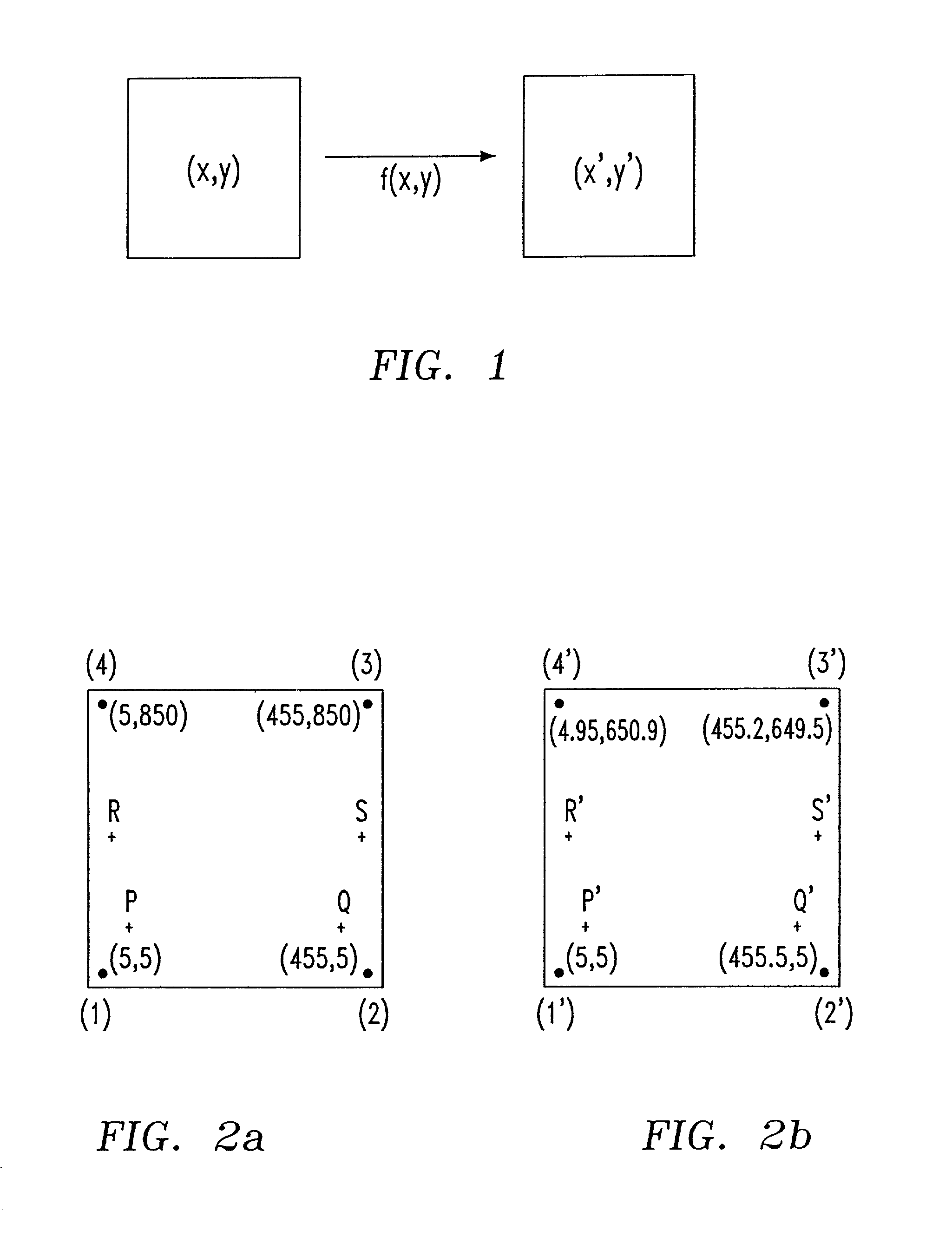
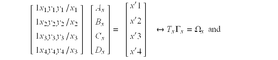
[0061] FIG. 2a shows the coordinates of the reference points (1), (2), (3), and (4) before the panel 12 is pressed. FIG. 2b shows the actual coordinates of these points on panel 14 after pressing. Using equations (5) and (6) to determine the coefficients and substituting them into equations (3) and (4), there is obtained,

[0062] x=-5.1895(10).sup.-3+1.0011.sub.x-4.6942(10).sup.-4.sub.y-1.9595(10-).sup.-3y / x, and

[0063] y=-4.6562(10).sup.-3+0.99991.sub.y+1.9599(10).sup.-5.sub.x-8.9194(1-0).sup.-3y / x.

[0064] For instance, it is now intended to drill 4 holes at the following locations: P (10, 10), Q(450,10), R(5,332.5), and S(455,322.5). The correct coordinates, in the drill program, should be: P' (9.9992, 9.9955), (Q'(450.4851, 9.9954), R'(4,7225, 32.7805), and S'(455.3425,322.2203).

[0065] Computing the angle between the line P'Q' and R'S'. Equation of the line passing P'Q' is y=-2.2702(10).sup.-7x+9.9955, and equation of the line passing R'S' is y=1.2432(10).sup.-3x +322.78. Take two ve...


PUM


Abstract

A method of creating a mathematical model which is employed in the determination of at least one work location in a multi-layered laminated circuit panel. The mathematical model for modifying drill data takes into consideration translational and rotational compensations caused by the encountered stretching or shrinking of the multi-layered panel subsequent to pressing or due to thermally processing, whereby the mathematical model may be utilized to modify drill data in order to accurately predict hole or via locations.

Description

[0001] 1. Field of the Invention[0002] The present invention relates to a method of creating a mathematical model which is employed in the determination of at least one work location in a multi-layered laminated circuit panel. More particularly, the invention is directed to the creation of a mathematical model for modifying drill data which takes into consideration translational and rotational compensations caused by the encountered stretching or shrinking of the multi-layered panel subsequent to pressing or due to thermally processing, whereby the mathematical model may be utilized to modify drill data in order to accurately predict hole or via locations.[0003] In the implementation of pressing and / or thermal processes employed in producing multi-layered panels for semiconductor packages, such panels frequently will stretch or shrink in non-uniformly translational and rotational aspects, and consequently may be the source of erroneous locations in the formation of holes or vias whi...

Claims


Application Information

Patent Timeline
IPC IPC(8): H05K1/02H05K3/00H05K3/46
CPCH05K1/0269H05K3/0008H05K2201/09918H05K3/4638H05K3/0047
Inventor NGUYEN, MANH-QUAN TAM
Owner IBM CORP
Why Eureka
Try Eureka