Path fault recovery method, switching-back method after recovery from fault, and node using the same

a fault recovery and path technology, applied in the field of path fault recovery methods, can solve the problems of requiring quick fault recovery, paths may not meet the requested fault recovery time, and delay the start of the fault recovery operation

Inactive Publication Date: 2003-07-24
NEC CORP
View PDF5 Cites 80 Cited by
  • Summary
  • Abstract
  • Description
  • Claims
  • Application Information

AI Technical Summary

Problems solved by technology

Further, in the fault recovery method of the "1:1" method and the "Shared" method described in Document 2, when a plurality of paths is set in a fault section, some of the paths may not satisfy a requested fault recovery time.
This is because the order of fault recovery is not managed on each node and thus a fault recovery operation may be started from a path not requiring quick fault recovery, thereby delaying the start of a fault recovery operation for setting fault recovery of the other paths requiring quick fault recovery.
Moreover, in the fault recovery steps of the "1:1" method and the "Shared" method de...

Method used


Image

  • Path fault recovery method, switching-back method after recovery from fault, and node using the same
  • Path fault recovery method, switching-back method after recovery from fault, and node using the same
  • Path fault recovery method, switching-back method after recovery from fault, and node using the same

Examples


Embodiment Construction

of the present invention.

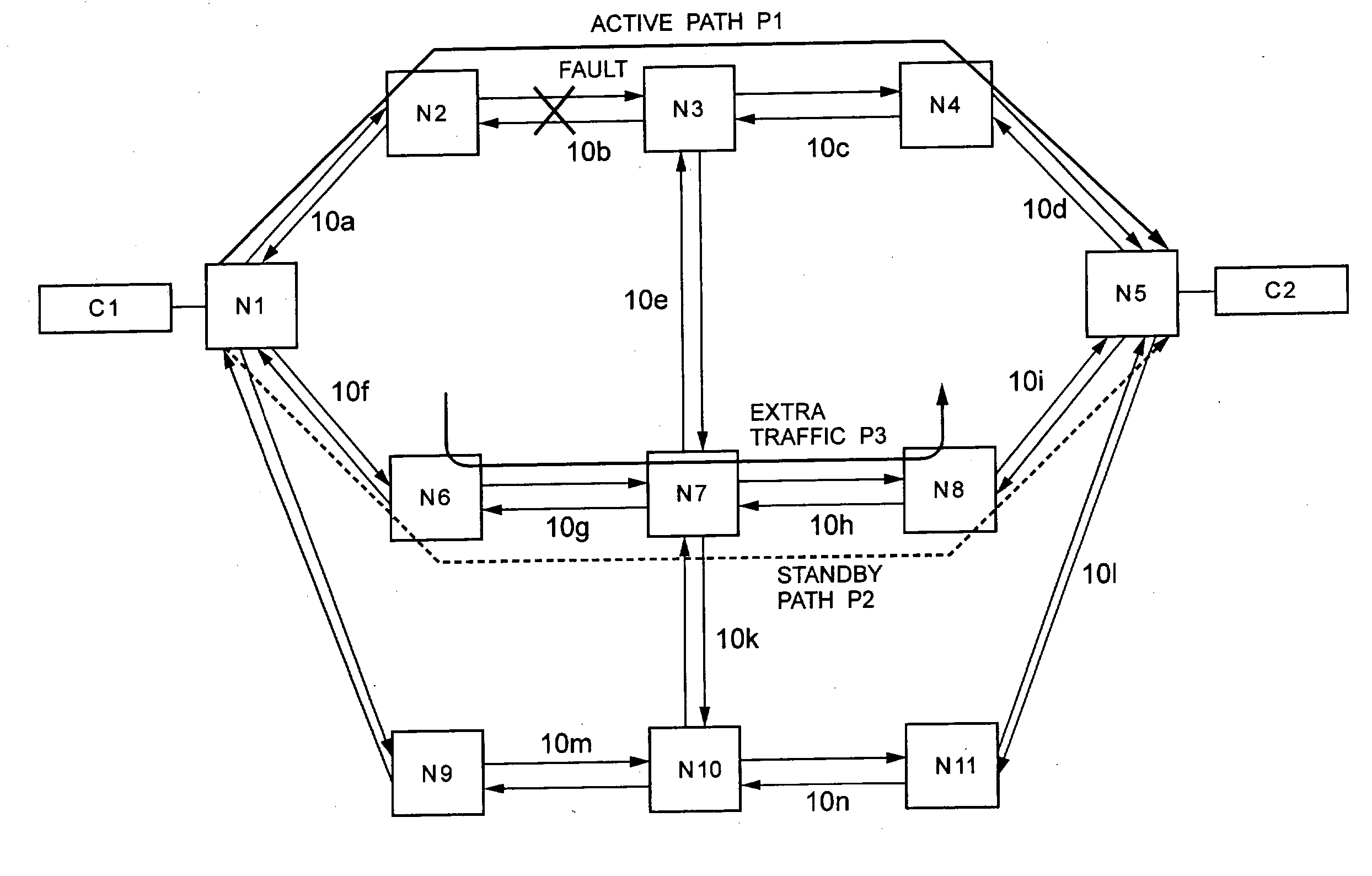
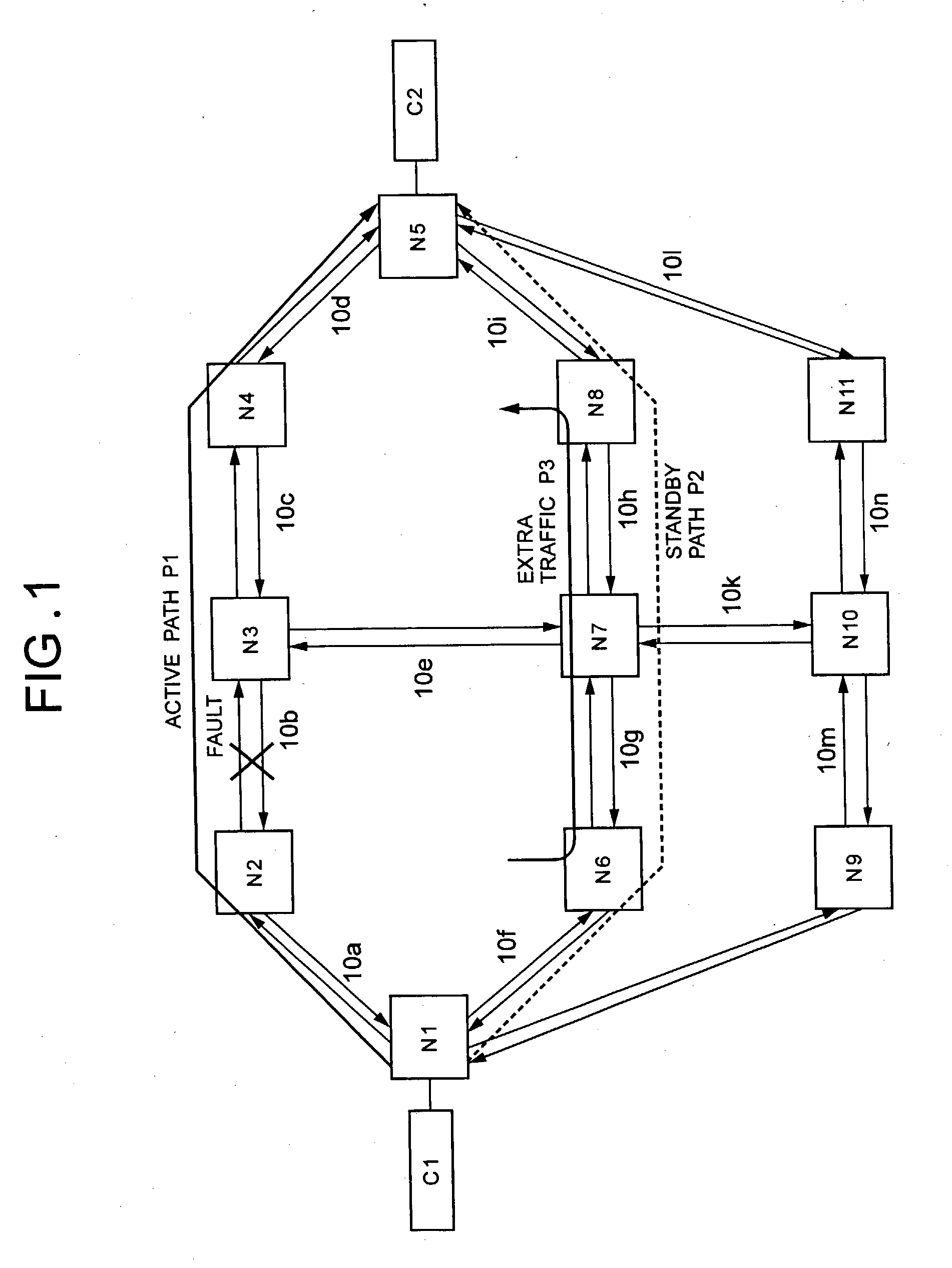
[0108] FIG. 10 is a diagram showing an operation of a fault recovery method according to Example 3 of the present invention. FIG. 11 is a flowchart showing the steps of setting switches according to Example 3 of the present invention. A network and nodes used in Example 3 of the present invention are identical in configuration to those of Example 1 of the present invention as shown in FIGS. 1 and 2. Further, the route of a standby path P2 is also identical to that of Example 1 of the present invention as shown in FIG. 3.

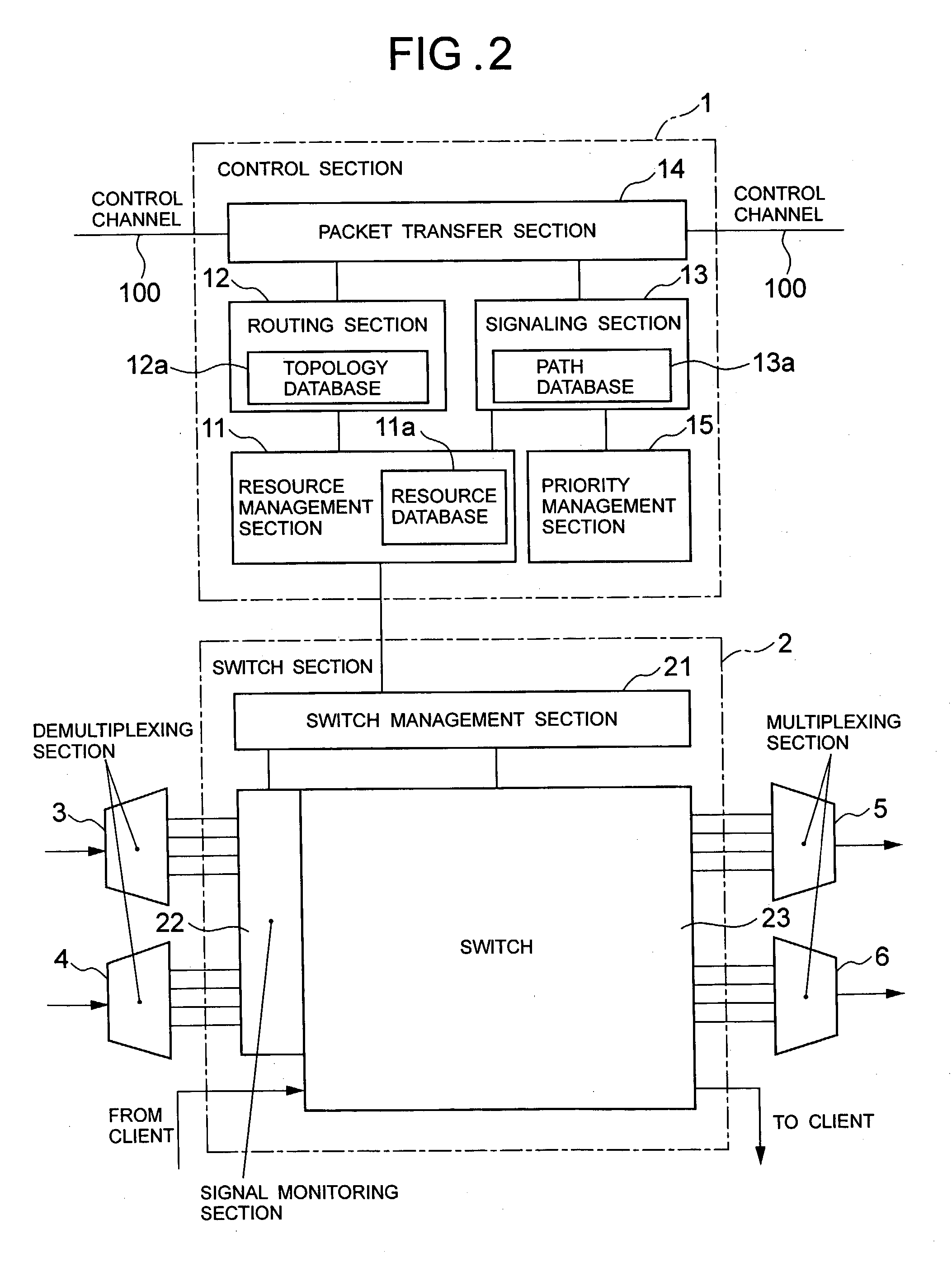
[0109] First, the following will discuss a notifying method according to Example 3 of the present invention when a fault occurs. As with Example 1 of the present invention, when a fault occurs on the optical fiber 10b on a two-way active path P1 in Example 3 of the present invention, a signal monitoring section 22 in a node N2 and a node N3 detects the fault, and the fault information is notified along the active path P1 from a start point no...


PUM


Abstract

This invention provides another optical path fault recovery method by which when the resources of a standby path are used by extra traffic, the standby path can be set quickly and an active path can be switched to the standby path without any improper connection in the event of a fault on the active path. An end point node of a path having received fault notification issues a resource securing request message transferred hop by hop to a start point node along the standby path. In the case where resources of the standby path are secured, when the resources are used by the extra traffic, the nodes on the standby path and the start point node that have received the message release the extra traffic and then secure the resources. When the resource securing request message reaches the start point node, the start point node issues a switch changeover request message, and the end point node, the start point node, and the nodes on the standby path set switches according to the secured resources.

Description

[0001] 1. Field of the Invention[0002] The present invention relates to a path fault recovery method, a switching-back method after recovery from a fault, and a node using the same, and particularly concerns a fault recovery method for an optical path using a signaling message in an optical network and a switching-back method for an optical path after recovery from a fault.[0003] 2. Description of the Prior Art[0004] As to an optical network constituted by an OXC (Optical Cross-connect) and an ADM (Add / Drop Multiplexer) or a SONET / SDH XC (Synchronous Optical Network / Synchronous Digital Hierarchy Cross-connect), a conventional example of a fault recovery method in the event of a fault on an active path is described in "draft-ietf-ccamp-gmpls-architecture-01.txt" (hereinafter, referred to as Document 1) which is an Internet draft of IETF (Internet Engineering Task Force). The fault recovery method for switching an active path and a standby path in Document 1 is further classified as "...

Claims


Application Information

Patent Timeline
IPC IPC(8): H04B10/03H04L45/24H04J3/00H04Q11/00H04Q11/04
CPCH04J2203/006H04J2203/0067H04Q2011/0039H04Q2011/0016H04Q2011/0024H04L41/0668
Inventor NISHIOKA, ITARUSUEMURA, YOSHIHIKO
Owner NEC CORP
Why Eureka
Try Eureka