Pyrolysis system

a technology of pyrolysis and system, which is applied in the direction of mixers, combustion processes, lighting and heating apparatuses, etc., can solve the problems of large system size, difficult control of reaction, and different pyrolysis technology from conventional incineration

Inactive Publication Date: 2003-07-24
STRUDES
View PDF16 Cites 50 Cited by
  • Summary
  • Abstract
  • Description
  • Claims
  • Application Information

AI Technical Summary

Problems solved by technology

Pyrolysis technology is different from conventional incineration, because air or oxygen is not used in the pyrolysis conversion process.
Most such systems permit the entry of air into the reactor, which makes the contr

Method used


Image

  • Pyrolysis system
  • Pyrolysis system
  • Pyrolysis system

Examples


Embodiment Construction

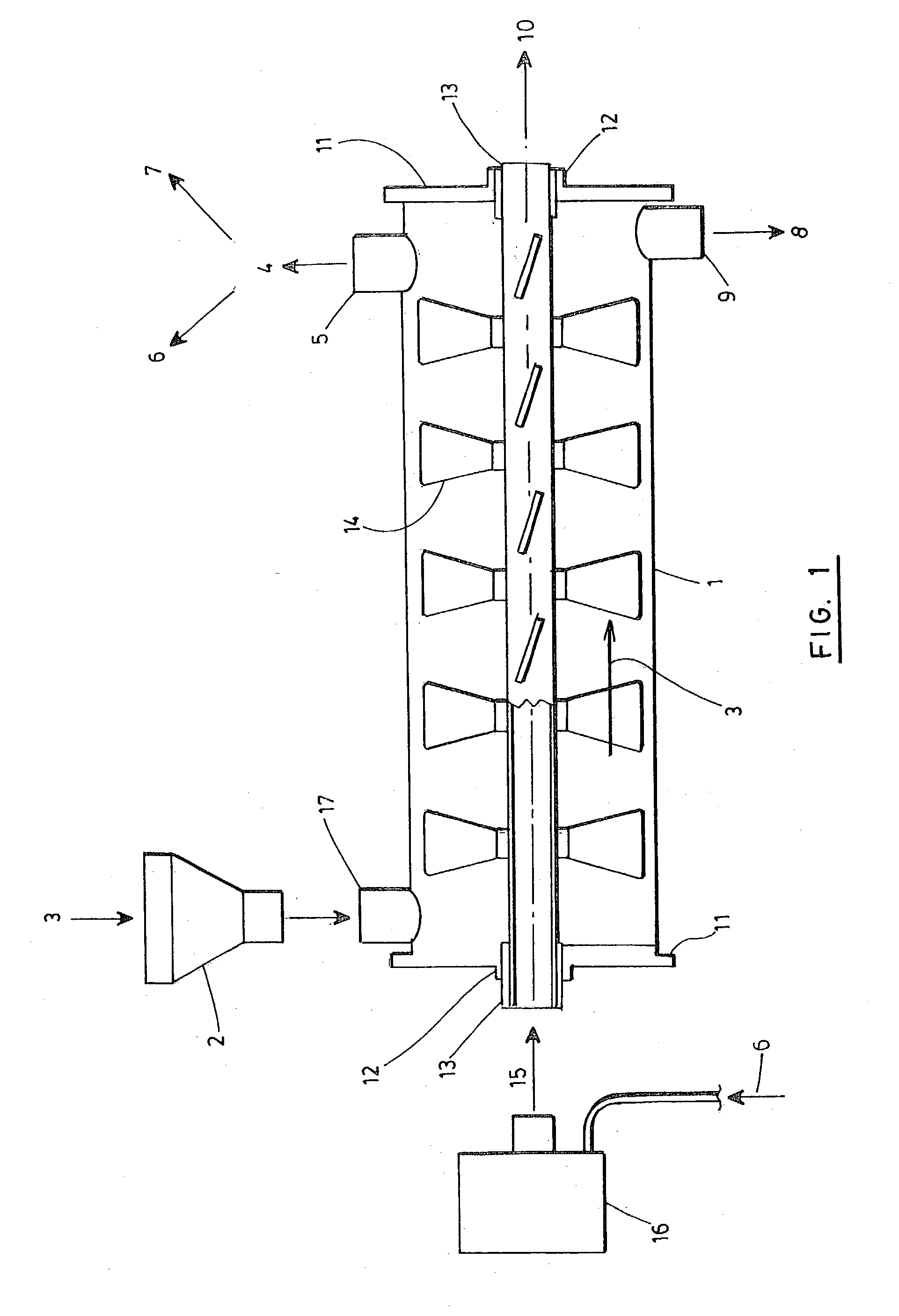
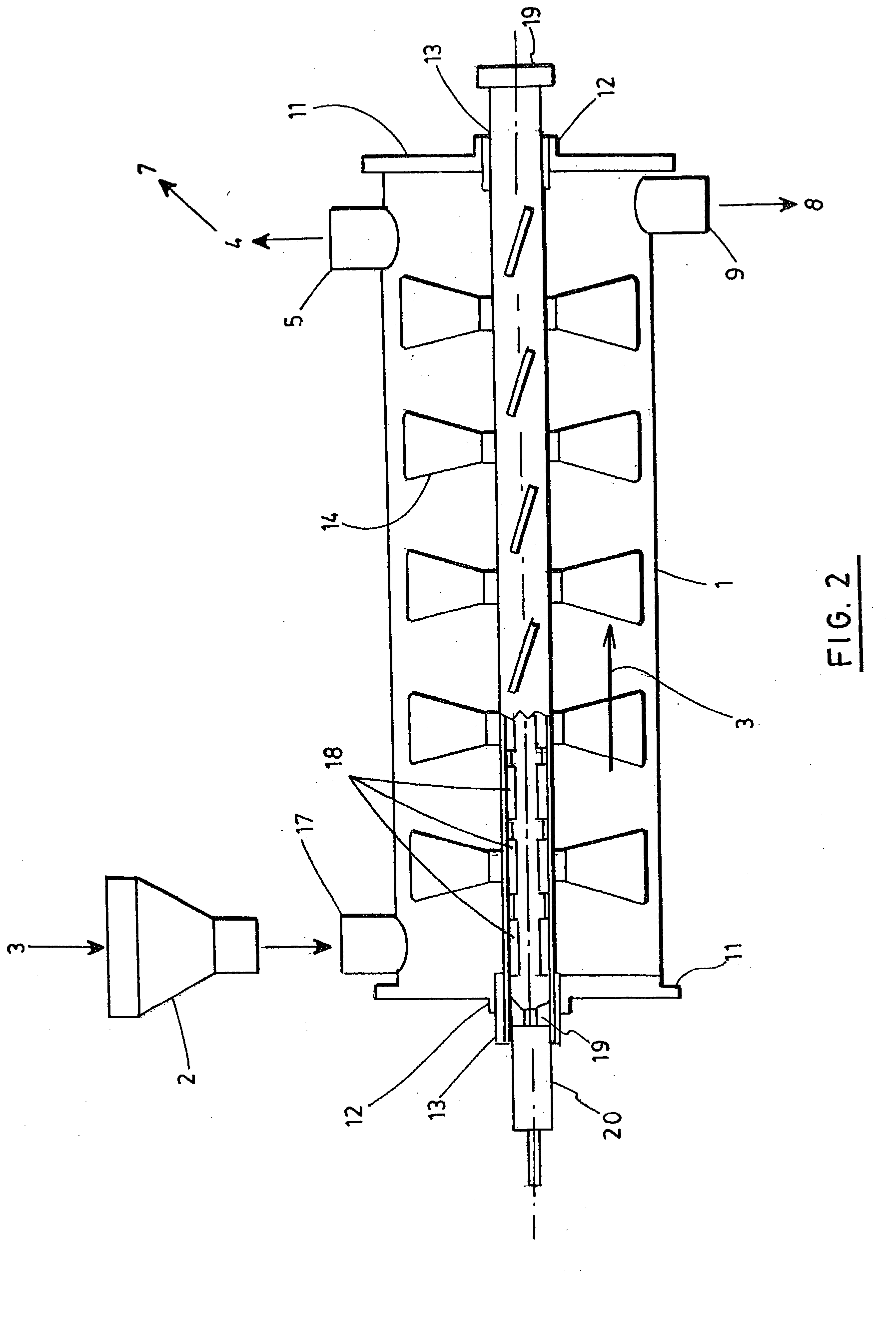
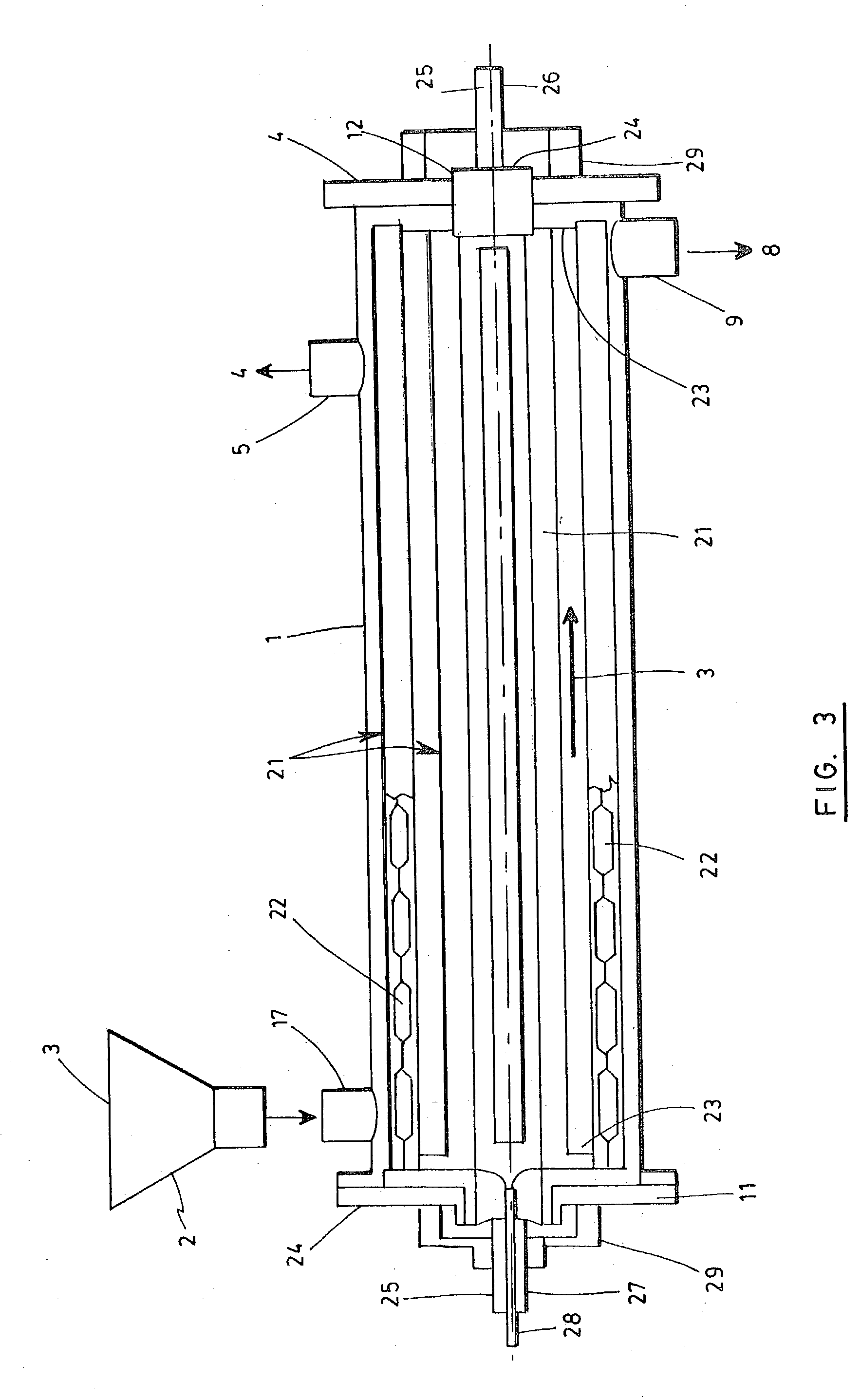
[0017] The system of the present invention is designed to be a compact and automatic conversion system of biomass into usable fuels. All the components are tested and pre-assembled on a platform and ready to start operation upon delivery.

[0018] The automation and portability of this system reduces transport and installation time which helps reduce costs. The system contains a pyrolysis reactor unit which is smaller and more efficient than conventional reactors. The efficiency is achieved by using a new design consisting of a heated rotor inside of a stationary pyrolysis chamber shell. Biomass is injected at one end into the chamber through a gas tight air-lock, and is then subjected to indirect heating supplied by a heated rotor that decomposes the biomass in the absence of air or oxygen into a biogas and charcoal. The biomass is never burned but decomposed. Biogas generated inside the reactor's chamber is extracted from the system and is used by itself, or in conjunction with an ex...


PUM

PropertyMeasurementUnit
Temperatureaaaaaaaaaa
Energyaaaaaaaaaa

Abstract

A pyrolysis system includes a generally cylindrical reactor chamber having two opposite ends and a longitudinal axis. The chamber has an inlet for receiving biomass, the inlet being adapted to prevent air from entering the chamber and being located at a first opposite end; a gas outlet for recuperating biogas produced in the reactor chamber, the gas outlet being adapted to prevent air from entering the chamber and being located at a second opposite end; and a solid outlet for recuperating charcoal produced in the reactor chamber, the solid outlet being adapted to prevent air from entering the chamber and being located at the second opposite end. The biomass is then subjected to indirect heating supplied by a heated rotor that decomposes the biomass in the absence of air or oxygen into a biogas and charcoal. A controller for controlling a rate of feed of biomass, extracted carbon residue and a temperature inside the reactor chamber is also provided. In a preferred embodiment, the shaft is heated by a portion of the energy recuperated from the pyrolysis system.

Description

[0001] The present invention is directed to a pyrolysis system for converting biomass into usable fuels.DESCRIPTION OF THE PRIOR ART[0002] Bio-energy is derived from materials such as wood from forests, industrial forestry processes, agricultural and animal waste as well as industrial human residue. The energy value of biomass comes originally from solar energy- photosynthesis. The chemical energy stored in plants and animal all the way up the food chain as well as the waste that they produce. The production of biomass through photosynthesis is the only large-scale method for temporary storage of the sun's energy. The pyrolysis process reverses the process the plants use to grow; only water, nitrogen, CO2 and sunlight are required to produce this virtually unlimited renewable energy. Generated biogas contains mostly carbon and hydrogen based gases, which form compounds, many of which are combustible. The energy derived from biomass is a form of renewable solar energy. Using this ene...

Claims


Application Information

Patent Timeline
IPC IPC(8): C02F11/10F23G5/027F23G5/40F23G7/10
CPCC02F11/10F23G5/027F23G2900/50203F23G7/10F23G2203/601F23G5/40
Inventor OBIDNIAK, LOUISTETRAULT, JACQUESWALKER, JOHN
Owner STRUDES
Why Eureka
Try Eureka