Method and an apparatus for measuring flow rates

a flow rate and flow rate technology, applied in the direction of volume/mass flow by thermal effects, sensors, catheters, etc., can solve the problems of temperature dependence of the flow rate of blood, inability to estimate the deep body temperature directly, and inability to wash out heat, etc., to achieve convenient use and processing of data obtained during measuremen

Inactive Publication Date: 2003-07-24
SEJRSEN PER +4
View PDF3 Cites 0 Cited by
  • Summary
  • Abstract
  • Description
  • Claims
  • Application Information

AI Technical Summary

Benefits of technology

0072] The apparatus is in general preferably produced of ordinary mechanical and electrical components and it is preferably produced so as to make the processing of the data obtained during measurement easy handable in an accompanying computer program.
0073] The apparatus may be made easy to use, so that due to its simplicity in use it is usable for doctors, technicians, nurses, and non medical personnel working with circulatory physiology, theoretical gymnastics, and exercise physiology.

Problems solved by technology

This is undesirable and the .sup.133Xe-wash-out method has for ethical--and perhaps also for medical--reasons not been used for pregnant women and child patients.
A major disadvantage of the heat wash-out method is that the wash-out of heat is dependent on at least the temperature of the blood, tissue and the surroundings thereto.
Another problem involved in measuring flow rate by heat wash-out is that the surface of the skin--or in general the wall member--where heat is applied and the surrounding area F has to be held at a temperature guaranteeing that heat at least during the heat wash-out phase is not drained from the skin (or the wall member) to the ambience in order to have a correct measure of the transportation of heat done by the blood (or the fluid).
One major problem in connection with these prior art probes is the estimation of the deep body temperature which is not directly available.
Another major problem in connection with the prior art probe is connected to the temperature dependency of the flow rate of blood.

Method used


Image

  • Method and an apparatus for measuring flow rates
  • Method and an apparatus for measuring flow rates
  • Method and an apparatus for measuring flow rates

Examples


Embodiment Construction

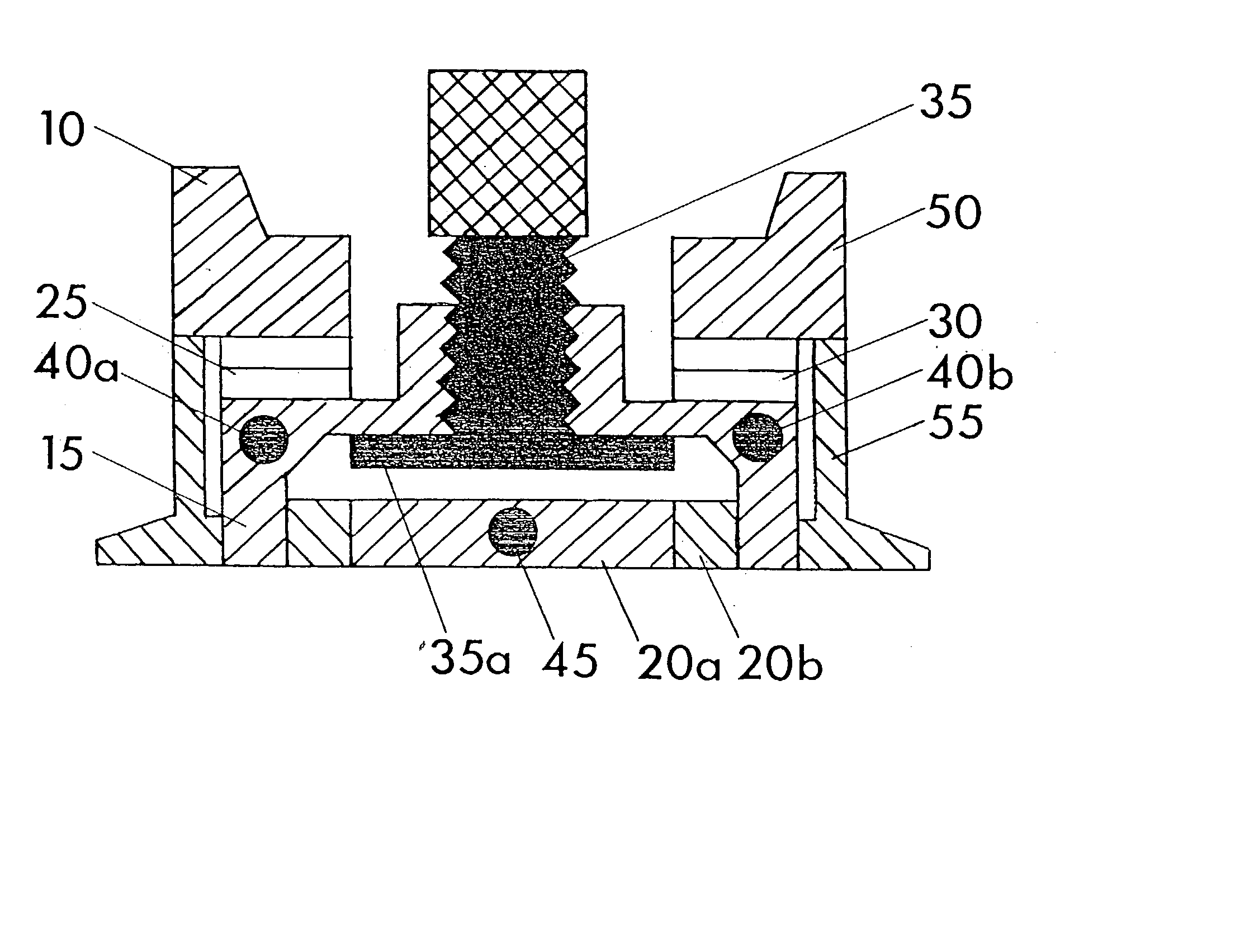
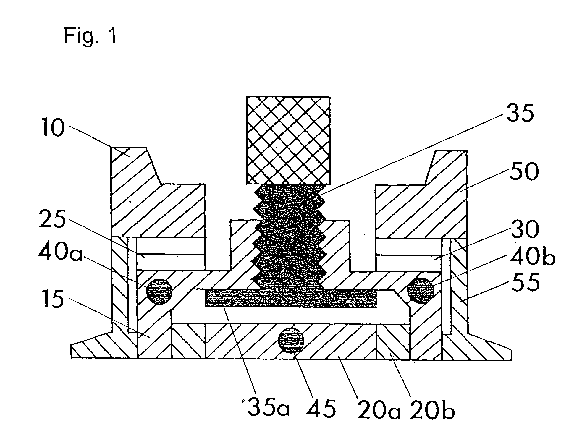
[0093] Principle of the Probe:

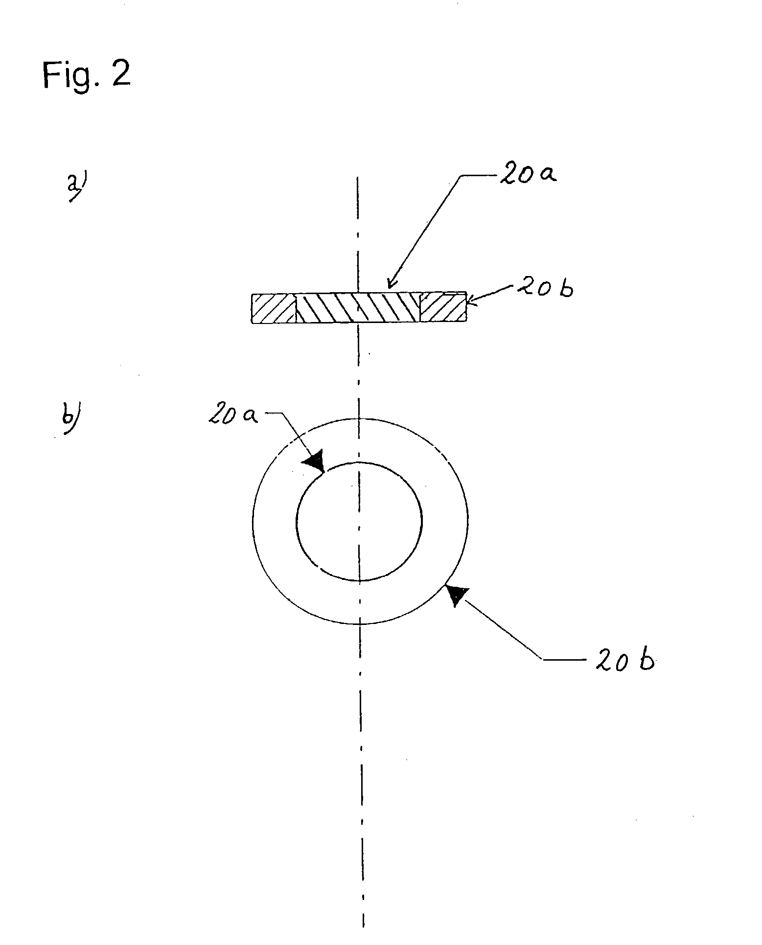
[0094] In FIG. 1 a presently most preferred embodiment of the apparatus, the probe, according to the present invention is depicted. The probe, indicated by numeral 10, comprises a cap 15, a measuring disc 20a, two Peltier elements 25, 30 and a movable metal bridge 35. The bridge 35 has an threaded part 35a which interacts with a thread provided in the bridge so the bridge may be dislocated in vertical direction upon rotation. Two thermistors 40a and 40b are contained in the cap. 15 and one thermistor 45 is contained in the measuring disc 20a.

[0095] In the presently most preferred embodiment of the apparatus according to the present invention two Peltier elements, 25 and 30, are placed in the cap 15 and are being used as heating and cooling elements. The function of the cap is to heat or cool both the measuring disc containing the thermistor 45 and the cutaneous tissue in contact with the probe. Furthermore the cap 15 has to remove surplus of heat or coo...


PUM


Abstract

An apparatus for measuring the flow rate of a fluid confined by a wall member, and wherein the apparatus comprises contacting means for contacting the wall member, the contacting means being formed of a material having a first heat transfer coefficient so that heat may be exchanged between the wall member and the contacting means. The apparatus further comprises heating means for supplying heat to and draining heat from the contacting means so that heat is being supplied to the wall member when heat is being supplied to the contacting means and so that heat is being drained from the wall member when heat is being drained from the contacting means. Bridging means for providing thermal contact between the heating means and the contacting means are provided.

Description

[0001] The present invention relates to a method and a device for measuring flow rates of a fluid being confined by a substantially non-penetrable wall member and relates in particular to measuring flow rates of blood streaming in tissue.BACKGROUND FOR THE INVENTION AND INTRODUCTION TO THE INVENTION[0002] Today measuring of blood flow rates in the human body is typical performed by adding .sup.133Xe to the tissue and afterwards measuring locally the decay of radioactive radiation, which experimentally has been correlated with the flow rate of the blood. This known method is referred to as the .sup.133Xe-wash-out method as the decay of radiation is governed by transportation of the radioactive isotope by the blood, i.e. the radioactive isotope is said to be washed out from the tissue.[0003] This method has some major disadvantages:[0004] The .sup.133Xe-wash-out method requires a frequent delivery of the radioactive isotope .sup.133Xenon which involves a considerable expenditure, abou...

Claims


Application Information

Patent Timeline
Patent Type & Authority Applications(United States)
IPC IPC(8): A61B5/00A61B5/026
CPCA61B5/026A61B5/01
Inventor SEJRSEN, PERMIDTTUN, METTE
Owner SEJRSEN PER
Why Eureka
Try Eureka