Heat insulating container

a technology of heat insulation container and heat insulation container, which is applied in the direction of domestic cooling apparatus, transportation and packaging, lighting and heating apparatus, etc., can solve the problems of deformation of heat insulation containers, unusable heat insulation containers, and deformation of inner and outer containers, and achieve excellent heat insulation performance and available volumetric space efficiency, so as to facilitate the washing process using a washing bath

Inactive Publication Date: 2003-08-07
NIPPON SANSO CORP
View PDF11 Cites 64 Cited by
  • Summary
  • Abstract
  • Description
  • Claims
  • Application Information

AI Technical Summary

Benefits of technology

0014] The present invention has been achieved in consideration of the above, and its object includes to provide a heat insulating container, which is excellent in heat insulating performance and available volumetric space efficiency, and which makes the washing process using a washing bath efficient by not floating on the bath water.

Problems solved by technology

These cause a problem of imparting to the user an impression of a small available volume (i.e., the available space is small relative to apparent size of the container).
Moreover, when the above-mentioned heat insulating container made of a synthetic resin having an insulating layer in which air or a gas having a low thermal conductivity is sealed as a heat insulating medium, is washed using, for instance, hot water, the air or gas expands due to the heat, and this causes deformation of the inner and outer containers making the heat insulating container unusable.
This problem of deformation stands out in particular when heat insulating containers for business use are washed using hot water, and then dried to be sterilized at high temperature.
Furthermore, when a large number of such heat insulating containers are washed, the containers to be washed are often immersed in a washing bath.
However, because the specific gravity of these containers is smaller than 1, the containers float on the water, and hence, it is difficult to remove food or drink stains on container walls.
This lowers the efficiency of the washing operation.
For the heat insulating container having a vacuum heat insulating layer, in particular, since container walls are always subject to atmospheric pressure, the container is required to have a thickness of 0.6 mm or more, otherwise buckling tends to occur when the container is dropped, and the container becomes practically unusable.
Therefore, if a heat insulating container made of a metal with a large opening portion is manufactured using a vacuum heat insulating structure, the manufacturing will be high with respect to its heat insulating performance, and the product would have no value as a commercial product due to the imbalance between its performance and its costs.
Also, when the heat insulating container made of a metal is used for holding a hot food or drink, the opening portion of the container is heated by the food or drink, and the user of the container cannot put his mouth directly to the container to intake the food or drink.
Moreover, if the container is used to serve a liquid containing a large amount of salt, such as miso soup, for a long period of time, a problem arises in that the surface of the container may rust due to contact with the miso soup.
Furthermore, when the container is washed after use with, for instance, hot water, the container as a whole is heated, and it is very inconvenient to handle the container after washing.
In addition, when the above-mentioned heat insulating containers made of a metal are manufactured as tableware, such as cups and bowls, the containers tend not to be readily accepted by users, compared with ordinary tableware, due to their less favorable appearance.

Method used


Image

  • Heat insulating container
  • Heat insulating container
  • Heat insulating container

Examples


example 2

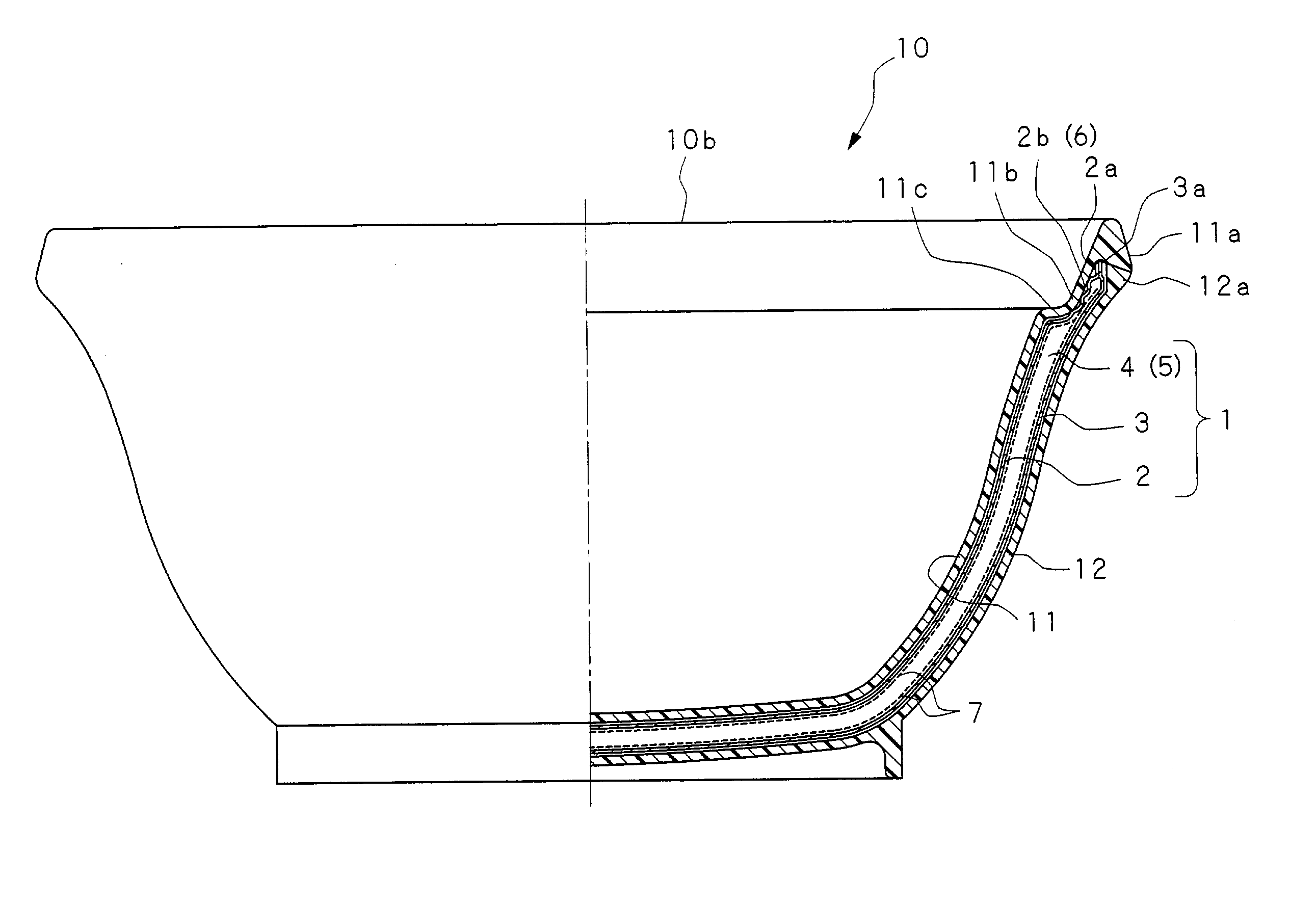
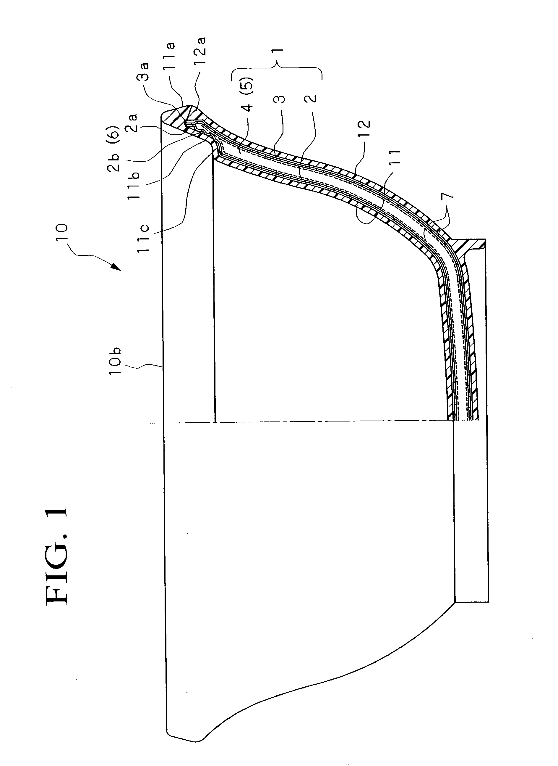
[0066] Next, the buoyancy of the heat insulating container of the present invention shown in FIG. 1 was confirmed by constructing three kinds of heat insulating containers (B), (C), and (D) whose size was varied as follows. Note that stainless steel SUS 304 was used for the inner wall member 2 and the outer wall member 3, and ABS (SR-H-35, a product of Denki Kagaku Kogyo K. K.) was used as a synthetic resin for the inside container part 11 and the outside container part 12. Also, copper foil was used for the radiation preventing layer 7.

[0067] Heat Insulating Container (B)

6 inner diameter of inner wall member 2: ca. 121.0 mm, thickness 0.3 mm outer diameter of outer wall member 3: ca. 136.0 mm, thickness 0.3 mm inner diameter of inside container ca. 119.4 mm, thickness 1.5 mm part 11: outer diameter of outside container ca. 142.0 mm, thickness 1.5 mm part 12: width of space portion 4 of heat 4.0 mm (inner size) insulating layer body 1: depth of inside container part 11: ca. 63 mm to...

example 3

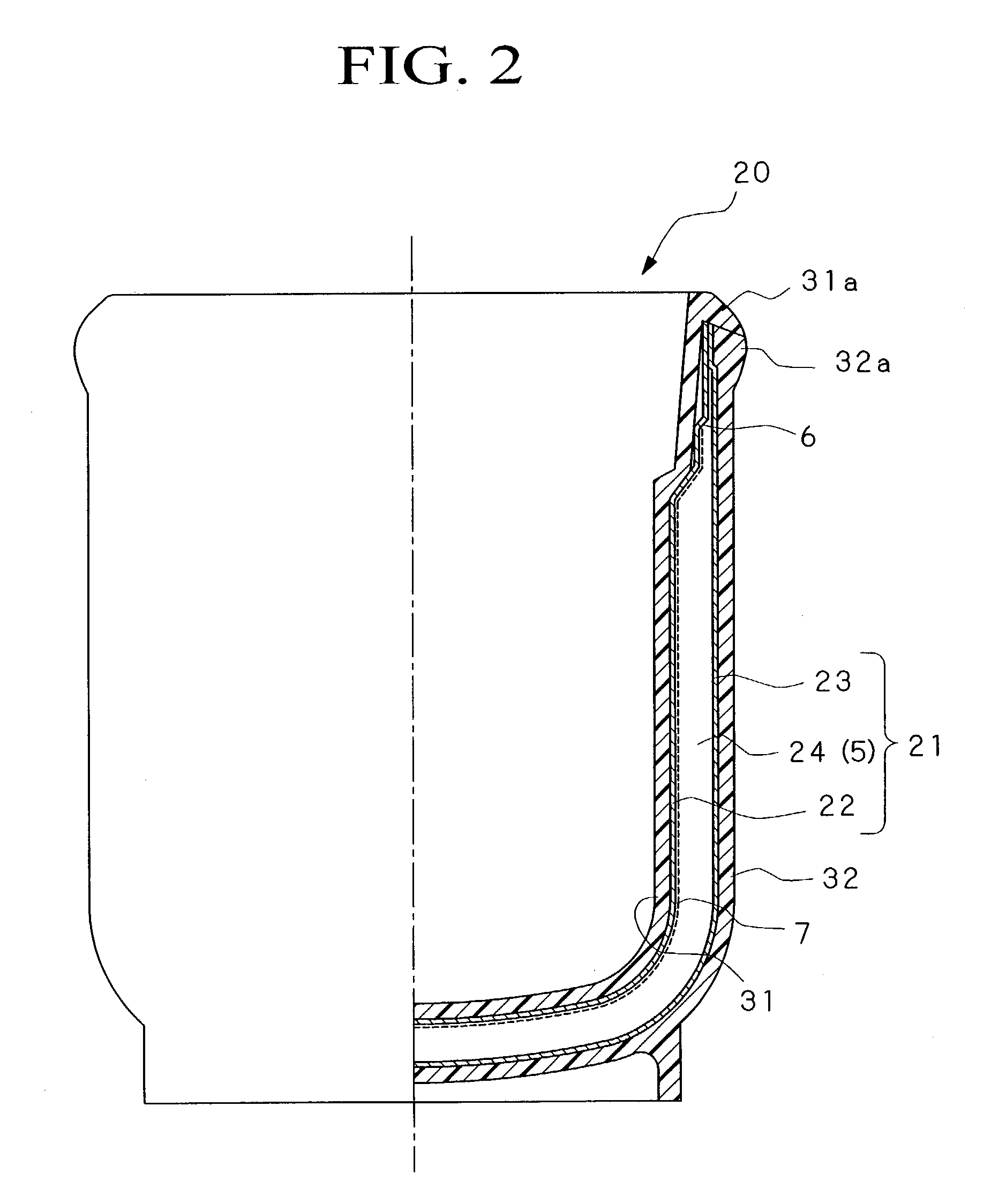
[0073] Also, as Example 3, an inner wall member 22 and an outer wall member 23 of a cup shape, which are made of a metal, such as stainless steel, were integrated with a space portion 24 therebetween as shown in FIG. 2, and the space portion 24 was evacuated to form an evacuated space 5 to produce a heat insulating layer body 21 of a cup shape. An inside container part 31 and an outside container part 32 made of a synthetic resin were placed so as to surround the heat insulating layer body 21. For this heat insulating container, the specifications of the inner wall member 22 and the outer wall member made of a metal were varied to produce three kinds of heat insulating containers (E), (F), and (G) using the same method, and the change in buoyancy thereof was confirmed.

[0074] Note that the inner wall member 22 and the outer wall member 23 were formed using SUS 304, and the inside container part 31 and the outside container part 32 were formed using polycarbonate (panlight L-1225T, a ...

example 4

[0082] Next, as a heat insulating container according to Example 4 of the invention, a heat insulating and retaining storage container 100 as shown in FIG. 3, which is suitable for holding and carrying food which is contained in non-insulated general tableware V, was manufactured using an insertion molding method. Note that in FIG. 3, elements which are the same as those in FIG. 1 are indicated using the same numerals, and the explanation thereof will be omitted.

[0083] The heat insulating and retaining storage container 100 includes a storage container part 40 having an upper opening portion, in which the container V, such as tableware, is placed, and a cover member 50 which covers an opening portion 40a.

[0084] The storage container part 40 includes an inner wall member 42 in a container shape, which is made of a metal, such as stainless steel, and an outer wall member 43 in a container shape, which has a similar shape to the inner wall member 42 but somewhat larger, and they are di...


PUM


Abstract

A heat insulating container having its outer surface formed of a synthetic resin such as a vacuum bottle, a cooler box, an ice box, a heat insulating cup, a heat retaining lunch box, and a heat insulating and retaining storage container capable of preventing problems such as a small available volume compared with a relatively large outer size so as to provide an increased insulating effect, corrosion of metallic containers, and inefficient washing of synthetic resin containers because the containers float in a water bath when washing; the heat insulating container having a metallic inner wall member 2 and a metallic outer wall member 3 disposed with a space portion 4 between them, the opening end portions 2a, 3a of these wall bodies being formed integrally with each other, and at least one of the inner and outer surfaces of a heat insulating layer body 1 formed by evacuating the space part 4 being covered by a synthetic resin inside container part 11 or an outside container part 12 and formed integrally with the heat insulating layer body so as to increase the specific gravity of the heat insulating container.

Description

[0001] The present invention relates to a heat insulating container which may be applicable to, for instance, a vacuum bottle, a cooler box, an ice box, a heat insulating cup, a heat retaining lunch box, and a heat insulating and retaining storage container.[0002] This application is based on Patent Application to the country of Japan (Japanese Patent Application No. 2000-110828), the content of which is incorporated herein by reference.[0003] Heat insulating containers made of metal or synthetic resins have been developed and manufactured for vacuum bottles, cooler boxes, ice boxes, heat insulating cups, heat retaining lunch boxes, heat insulating and retaining storage containers, and so forth because of their light weight, ease of molding, and low material and manufacturing costs.[0004] Among the above, for heat insulating containers made of a synthetic resin, an inside container made of a synthetic resin is disposed in an outside container, which is also made of a synthetic resin...

Claims


Application Information

Patent Timeline
Patent Type & Authority Applications(United States)
IPC IPC(8): A47J41/02B65D6/10B65D8/06B65D81/38
CPCA47J41/022B65D81/383B65D81/3818
Inventor FUJII, TAKAFUMIOTSUKA, EIJI
Owner NIPPON SANSO CORP
Why Eureka
Try Eureka