Optical waveguide amplifier using a circulator and an optical signal reflective surface and method employing same

Inactive Publication Date: 2003-08-21
MOLECULAR OPOTOELECTRONICS CORP
View PDF0 Cites 10 Cited by
  • Summary
  • Abstract
  • Description
  • Claims
  • Application Information

AI Technical Summary

Problems solved by technology

Thus, the number of nodes and access points is significantly higher than in the long-haul networks, requiring a large increase in the number of amplifiers required in these networks.
However, increased functionality translates into a higher component count, which results in higher component transmission losses.
Thus, because of both distance and component transmission losses, the number of amplifiers needed in the network architecture is increased as well as cost.
However, even though the cost of the device may be reduced

Method used


Image

  • Optical waveguide amplifier using a circulator and an optical signal reflective surface and method employing same
  • Optical waveguide amplifier using a circulator and an optical signal reflective surface and method employing same
  • Optical waveguide amplifier using a circulator and an optical signal reflective surface and method employing same

Examples


Embodiment Construction

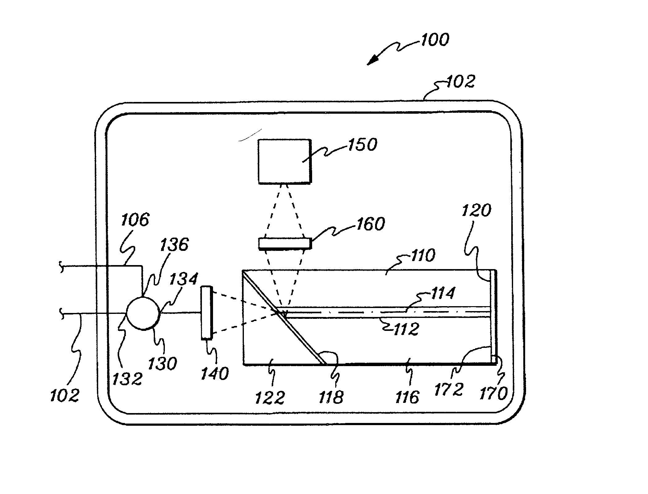
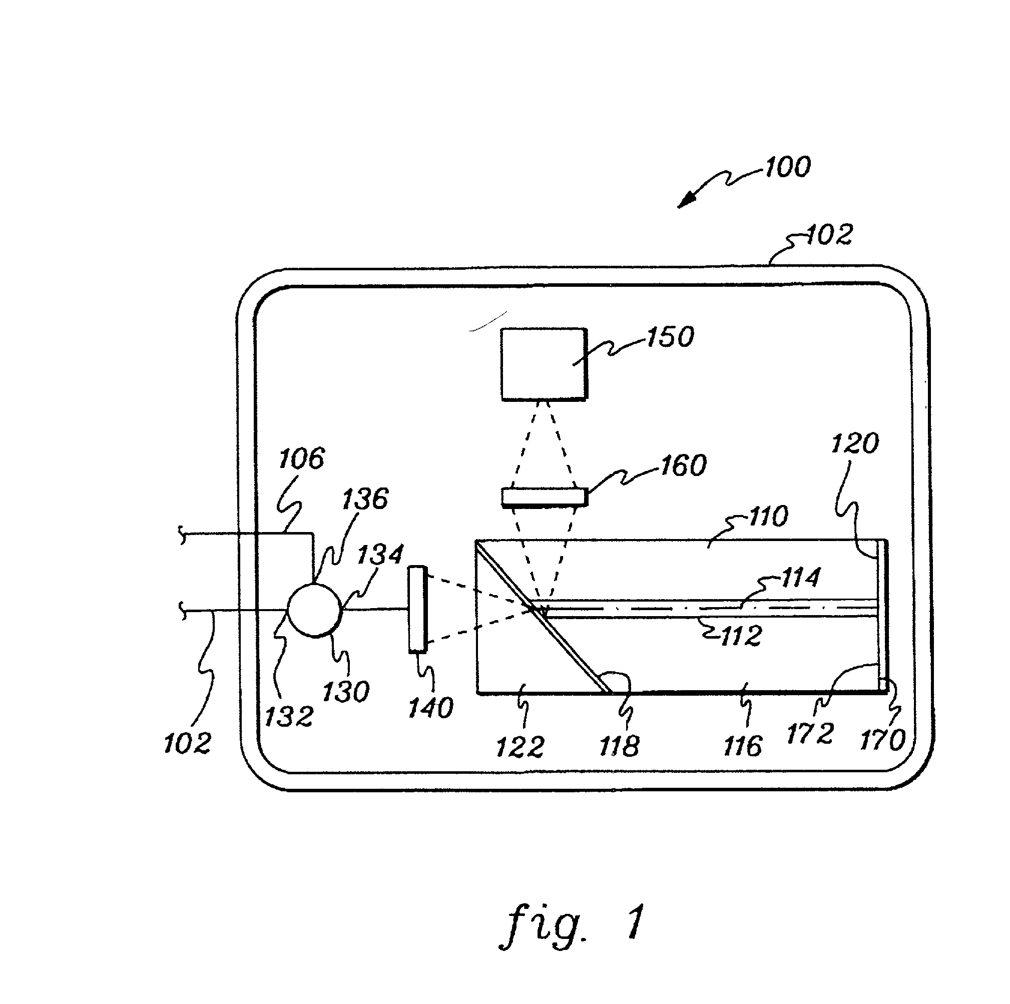
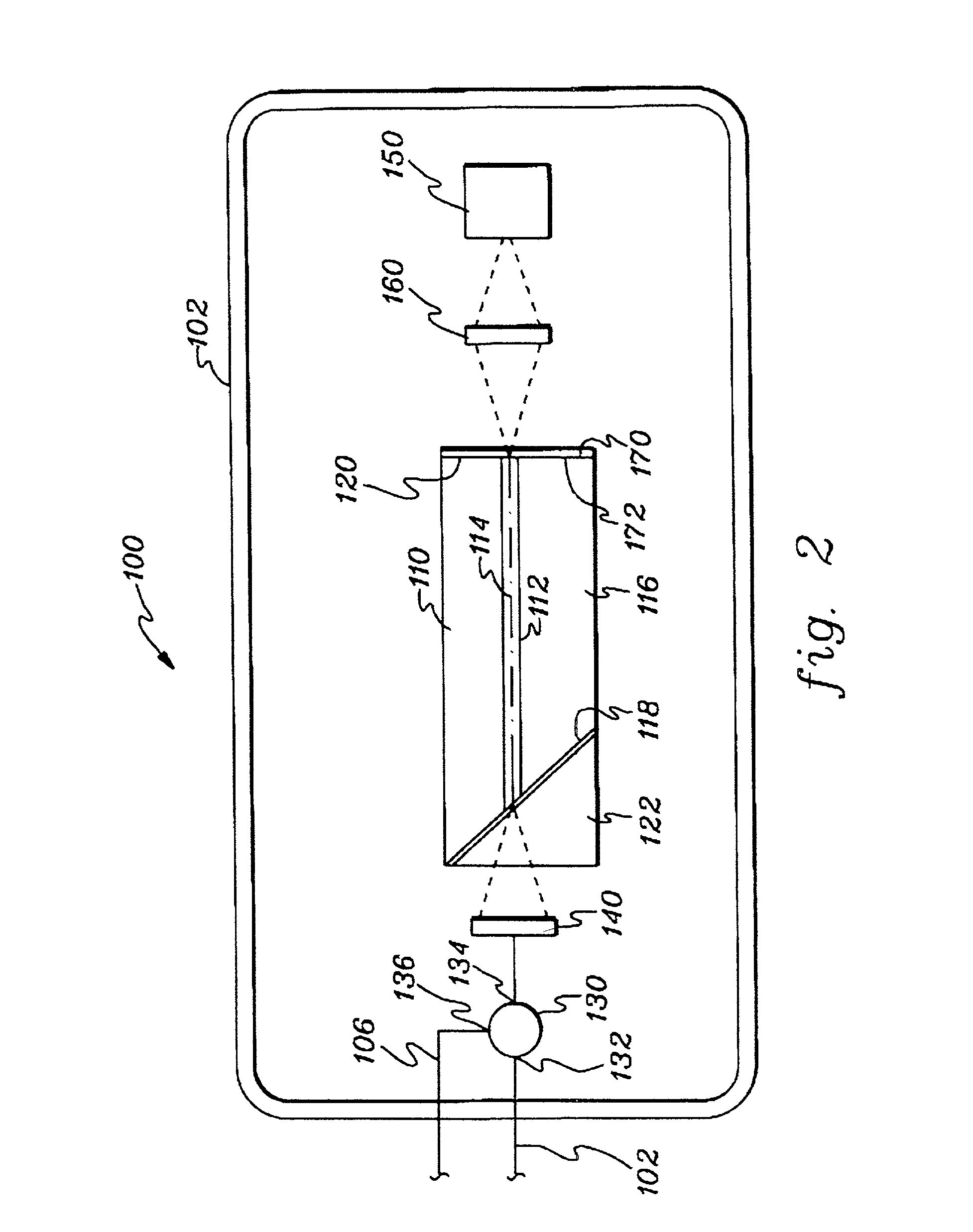
[0018] Generally stated, a novel waveguide amplifier employing a circulator and an optical signal reflecting surface is presented wherein stimulated emission is employed in a waveguide to amplify signals in a fiber-optic system. To summarize, the unique amplifier architecture allows for an optical signal to pass along the length of a waveguide a first time, reflect off an optical signal reflecting surface and then pass along the length of the waveguide a second time by using a circulator, splitter or other means positioned near an input end of the waveguide to receive the amplified signal exiting the input end of the waveguide. The optical amplifier made in accordance with the principles of the present invention results in a higher gain by subjecting the optical signal to twice the pump energy and twice the length of a waveguide at a lower cost without sacrificing other performance characteristics.

[0019] FIG. 1 depicts one embodiment of a waveguide amplifier 100 in accordance with t...


PUM


Abstract

An optical amplifier with integrated optical waveguide, pump source and other, optional components for amplifying an input optical signal. The amplifier includes a circulator and an optical signal reflective surface disposed at an end opposite an optical signal input receiving end of the waveguide which enables an optical signal to pass through the waveguide a second time exposing the optical signal to further amplification. The disclosed amplifier offers cost advantages and a higher gain without sacrificing other performance characteristics.

Description

[0001] The present invention relates to optical amplifiers, and more particularly to an optical amplifier using an optical circulator and optical signal reflecting surface with an optical channel waveguide.BACKGROUND OF INVENTION[0002] The field of optical telecommunications has experienced phenomenal growth over the past several years, fueled in large part by the development and deployment of erbium-doped fiber amplifiers ("EDFAs") which are capable of amplifying multiple wavelengths independently in a single unit.[0003] The deployment of EDFAs has traditionally been used in long distance or long-haul communication systems. In the long-haul market, optical amplifiers were designed for optimum performance and increased cost was tolerated and acceptable when traded off for desired operating characteristics. These networks were typically designed for point-to-point transmission, which limits the number of amplifiers required.[0004] The continuing growth of EDFAs has led to a new deman...

Claims


Application Information

Patent Timeline
IPC IPC(8): G02B6/42H01S3/063H01S3/094H01S3/0941H01S3/16H01S3/17
CPCG02B6/42G02B6/4214G02B6/4246H01S3/0621H01S3/0632H01S3/2333H01S3/094015H01S3/094084H01S3/09415H01S3/1608H01S3/175H01S3/0637
Inventor LAWRENCE, BRIAN L.FUERST, RUSSELLMANEY, THOMASSHAPIRO, ANDREWCLOW, LAWRENCEMENDRICK, MARKMACK, CHARLESCHEVERTON, MARK
Owner MOLECULAR OPOTOELECTRONICS CORP
Why Eureka
Try Eureka